Implementing a Simple Feedback Controller
Overview
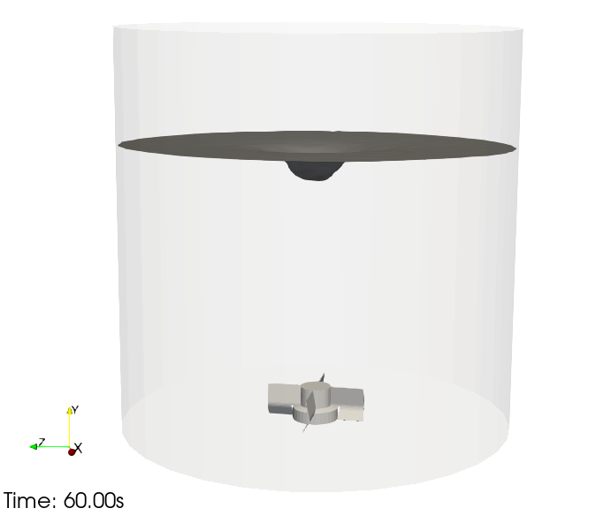
In this guide, we will learn how to establish a feedback-loop–controlled CFD setup. This method can be used to quickly find an optimal process parameter for a continuous output signal, like the power input or vortex depth, etc. This circumvents long characterization studies and reaches a specific goal with a single simulation. We will control the impeller speed to achieve and maintain a specified vortex depth in a simple unbaffled tank equipped with a bottom-mounted impeller.
Note
A prebuilt PID controller is available. We will write our own simple controller to fully understand how it works. (The Optimizer should be used for discrete output like mixing time or optimization of the geometry.)
Model Setup
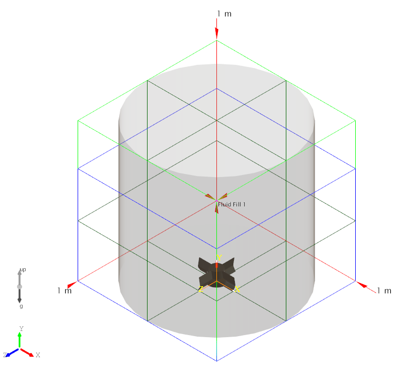
Let’s start by creating a Static Body. Select the Parametric Cylindrical Tank and change the bottom (End 1) to ‘Flat’. Let’s also change the Baffle Number to 0.
Now add the impeller: Non-Parametric > Impeller > Bottom mounted magnetic > Bottom mounted mag 250.
The setup should look like this:
Measuring Vortex Depth
We want to measure the vortex depth [m], define a setpoint, and control the impeller speed. We will need a few Global Variables (GVs) for that. Let’s start with the measurement of the minimum and the maximum of the Y-position of the free surface.
Create two Global Variables. As Data Source select ‘Interfaces’ for both, as the Reduction, select ‘Maximum’ and ‘Minimum’, and for the Code, select “value = y;” for both.
It looks like this for the maximum:
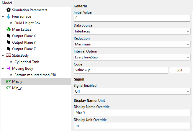
At this point you can optionally rename the global variables and override the display names and units.
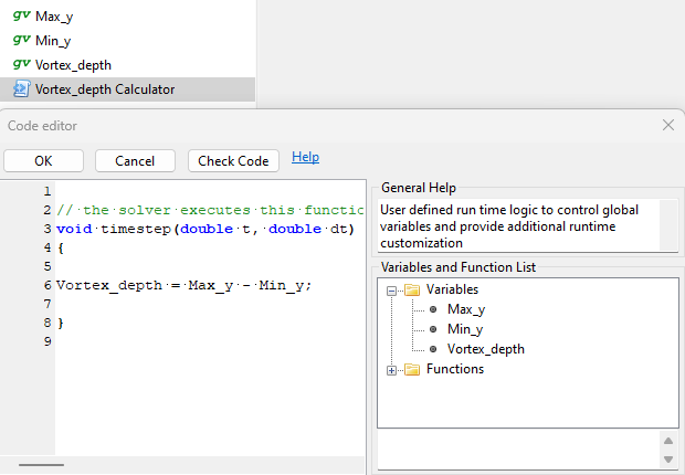
Calculate Vortex Depth
Now we want to calculate the vortex depth. Add another Global Variable and a Custom Script. Rename the GV ‘Vortex_depth’, for example, but don’t specify an initial value or data source because it will be overwritten by the calculator. Rename the Custom Script to something like ‘Vortex_depth_Calculator’.
This is where we can do a simple calculation of the vortex depth:
Now we measure the vortex depth. We only need to add the setpoint, the controlled impeller speed, and the controller itself.
Controller Implementation
Let’s add two more Global Variables and a Custom Script. Call one GV ‘Vortex_depth_Setpoint’ and change its Initial Value to ‘0.1’. We want the vortex to be 10 cm deep. You can also change the Display Name and Unit.
Add another Global Variable and call it ‘RPM’. Leave this one empty. The controller will overwrite it.
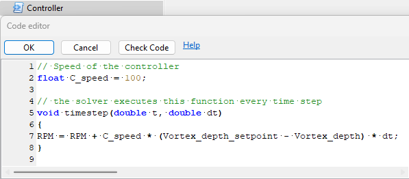
Add the Custom Script and rename it to ‘Controller’. This controller adds or subtracts a small margin to the impeller speed \(RPM_{t}\) each time step. This margin depends on the error (difference between measurement \(VD_{measured}\) and setpoint\(\ VD_{setpoint}\)), a constant to control the speed of the controller \(C_{speed}\), and the impeller speed from the last time step \(RPM_{t - 1}\). This will increase the RPM if the measured value is smaller than the setpoint and subtract if reversed.
We also multiply with the time step \(\Delta t\) to make the controller independent of the simulation time step because we are defining the adjustment per time step:
It looks like this in M-Star Pre:
Simulation Parameters
Let’s change some general settings before we start. Change the Resolution LX to ‘150’ and the time step (dt [s]) to ‘0.00015’ seconds:
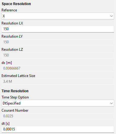
There is a problem with defining a good time step before we run the simulation because we don’t have a reference impeller speed or an inlet or outlet velocity. The time step could be calibrated to some maximum RPM in an industrial setting. Here, the time step was altered until it ran stable.
Running the Simulation
Now we can finally run the simulation and check if the controller works.
Results and Analysis
After running the simulation, we can plot the Global Variables in M-Star Post:
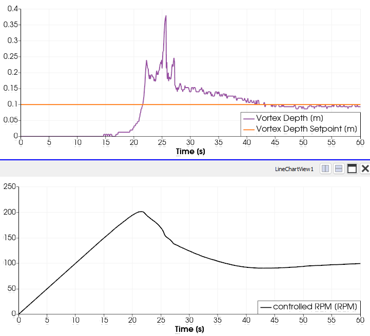
The controller increases the RPM when our vortex is smaller than the setpoint and decreases it when the vortex is too deep. The RPM overshoots because our controller is pretty fast, but it is not too fast to cause oscillations.
We reach our desired vortex depth of 10 cm with an impeller speed of 100 RPM. We did not need to run extensive parameter studies to find the right answer, only a single simulation.