 Edit Mesh
Introduction
The Edit Mesh form is used to edit the resolution of the surface mesh used in the simulation. Users can preview the mesh and select different mesh resolutions before running the solver. Any geometry imported into the pre-processor as a surface file is automatically converted to a triangular mesh, which is then used by the solver during the simulation.
The mesh determines the fidelity with which the geometry’s topology is represented. In most simulations, the final surface mesh resolution should roughly align with the spatial resolution of the lattice domain. Increasing the mesh resolution beyond the lattice resolution typically provides little benefit and can unnecessarily increase simulation cost.
Surface mesh resolution most notably affects the visual quality of Static Body Variables and Moving Body Variables. If the mesh is too coarse, the exported geometry may appear faceted. If the mesh is excessively fine, it increases computational work without improving the physical accuracy of the simulation. In general, users should avoid using a finer surface mesh than necessary.
One important exception occurs when using the Triangle Bounce Method for DEM particles. In this mode, DEM particles interact directly with the triangular surface mesh generated by the solver. Because particle collisions are computed against these triangles, a finer mesh may be required to accurately represent curved or complex surfaces.
Outside of this case, relatively coarse surface meshes are usually sufficient, since the primary role of the mesh is geometric representation rather than controlling the fluid-physics resolution.
Note
Mesh files are imported in their existing tessellated form and passed directly to the solver without modification. Edit mesh command is not available for these child geometry types.
Access
When you select Edit Mesh on the applicable context-specific toolbar, the form below will launch.

Edit Mesh Form
M-Star CFD provides two algorithms for generating a surface mesh from a model, Advanced and Standard.
Mesh Algorithm
- ○ Standard
Provides a robust, general-purpose solution for surface meshing. It generates triangular meshes using controls based primarily on linear deflection and angular deviation parameters, prioritizing reliability over fine-grained precision.
- ○ Advanced
Enables more granular control over the mesh, utilizing surface element size functions and advanced algorithms. The result is a high-quality mesh with well-shaped elements, ideal for simulations requiring greater surface fidelity.
Mesh Parameters:
Standard
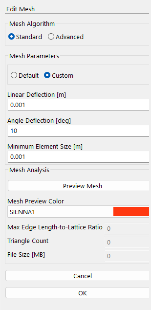
The Standard algorithm creates triangular meshes that approximate complex shapes while balancing accuracy, mesh density, and processing speed through user-defined parameters. It is a robust meshing engine designed to handle poorly defined or highly complex geometries where the Advanced Mesh engine may struggle. Although it is less exact and offers fewer precision controls than Advanced Mesh, Standard Mesh is generally more tolerant of imperfect geometry, making it a strong choice when the top priority is to generate a valid mesh.
Users can configure the mesh by selecting one of two parameterization settings:
- ○ Default
Automatically generates a relatively low resolution mesh.
- ○ Custom
User manually defines all mesh parameters.
The mesh is defined by up to three parameters that control element size, geometric fidelity, and curvature resolution. Standard Mesh uses these settings as guidelines but may relax overly strict values (for example, when deflection is smaller than the model’s tolerance) to improve stability.
- Linear Deflection
m | This sets the maximum distance between the mesh surface and the original CAD geometry, measured along the surface normal. Lower values generate meshes that better follow the geometry with more, smaller triangles. Higher values loosen that tolerance and produce fewer, larger elements. This point is illustrated in the image below. Universal Mesh respects this parameter, but it may relax the setting to ensure a valid result. The default value is set to 0.001 m.

- Angle Deflection
deg | This controls how much the normals of adjacent mesh triangles can deviate from the CAD surface normals. Lower values keep the mesh denser in curved areas and preserve more surface detail. Higher values simplify flat regions by using fewer elements. This point is illustrated in the image below. Standard Mesh follows your setting as much as possible, but if perfect curvature tracking would prevent meshing, it prioritizes creating a valid mesh over exact fidelity. The default value is set to 0.5 radians.

- Min Element Size
m | This defines the smallest allowable edge length for any mesh element. Lower values preserve tiny features and sharp details, while higher values skip over small geometry to simplify the mesh and speed up processing. This point is illustrated in the image below. Standard Mesh will attempt to honor this limit, but if extremely small elements would make meshing unstable, it may override the setting. The default value is set to 0.0001.

The Default option automatically configures the meshing parameters based using the values summarize in the table below.
Setting |
Min Element Size (m) |
Linear Deflection (m) |
Angular Deflection (rad) |
|---|---|---|---|
Default |
0.001 |
0.001 |
20 |
The Custom setting allows users to manually define all mesh parameters, bypassing these automatically configured values.
Mesh Parameters
Advanced:
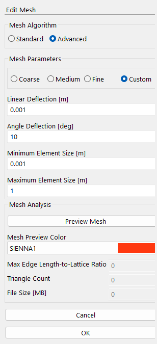
The Advanced mesh algorithm is a high-performance meshing engine based on the Express Mesh algorithm developed by Open Cascade S.A.S. It generates precise triangular surface meshes from CAD geometries, offering fine control over accuracy, density, and processing speed through user-defined parameters.
Users can configure the mesh by selecting one of four parameterization settings:
- ○ Coarse
Automatically generates a relatively low-resolution mesh.
- ○ Medium
Produces a balanced mesh suitable for general simulations.
- ○ Fine
Creates a high-resolution mesh for increased fidelity.
- ○ Custom
Allows users to manually define all mesh parameters.
The mesh is defined by up to four parameters that govern element size, geometric fidelity, and curvature resolution.
- Linear Deflection
m | This defines the maximum allowed distance between the generated mesh surface and the actual CAD geometry, which is measured along the surface normal. Lower values produce higher surface fidelity with more elements. Higher values produce fewer elements. Choose smaller deflection for high-accuracy STL exports or simulation meshes. The default value is set to 0.001m. This default value was chosen to balance fidelity and performance for most CAD geometries.

- Angle Deflection
deg | This defines the maximum allowed angular deviation between the normals of adjacent mesh elements and the CAD surface normals. Lower values preserve curvature details by generating denser meshes in curved regions. Higher values produce fewer elements and are suitable for flat or low-curvature surfaces. The default value is set to 20 degrees. This default value was chosen to maintain a good balance between accuracy in curved regions and efficiency on flat surfaces.

- Minimum Element Size
m | This defines the smallest allowable edge length for any mesh element and ensures fine geometric features are captured without generating unnecessarily tiny elements that would slow down processing. Lower values are useful for preserving small details; higher values ignore minor features to simplify the mesh. The default value is set to 0m, implying no minimum element size.

- Max Element Size
m | This defines the largest allowable edge length for any mesh element, prevents oversized elements on flat or cylindrical surfaces, and promotes uniform mesh density. Lower values enforce consistent element sizes, while higher values allow larger facets for faster meshing on simple geometries. For most surfaces, the Max Element Size parameter has the strongest influence on overall mesh quality and size. This parameter should be correlated to the lattice spacing, dx. Typical values for this parameter range from 2*dx (for a fine surface mesh) to 20*dx, (for coarse surface mesh).

The Coarse, Medium, and Fine options automatically configure the meshing parameters based on a predefined relationship with the baseline resolution dx defined in the model. The table below summarizes the parameters used for each setting:
Setting |
Max Element Size (m) |
Min Element Size (m) |
Linear Deflection (m) |
Angular Deflection (rad) |
|---|---|---|---|---|
Coarse |
20*dx |
0 |
0.001 |
20 |
Medium |
10*dx |
0 |
0.001 |
20 |
Fine |
2*dx |
0 |
0.001 |
20 |
For these three automatically configured settings, the maximum element size scales with the baseline resolution dx. When one of these settings is selected, the solver calculates the maximum element size dynamically based on the current dx value.
The Custom setting allows users to manually define all mesh parameters, bypassing the automatically configured values.
Note
Mesh properties do not automatically update when the baseline resolution dx changes. To regenerate the mesh using one of the predefined settings after updating dx, reopen this form and reselect the desired parameterization option. The solver will then recalculate the mesh based on the updated dx.
Mesh Analysis
- Preview Mesh
This button displays the output of the meshing algorithm, providing both a visual representation and quantitative metrics. The preview displays the surface mesh generated by the meshing algorithm, overlaid on the underlying CAD geometry in the viewing panel. Users can visually inspect element density, distribution, and alignment with geometry.
- Mesh Preview Color
The mesh color can be customized by clicking the Mesh Color button to improve visibility and contrast against the solid surface.
- Max Edge Length-to-Lattice Ratio
This metric reports the ratio between the maximum triangle edge length and the model’s baseline resolution dx:
\[\text{Max Edge Size Ratio} = \frac{\text{Maximum Triangle Edge Length}}{dx}\]This value represents an upper bound on how many lattice points are mapped onto each triangular element. Smaller values (≈ 2–5) mean less interpolation between the lattice and surface mesh; recommended for systems with interpolated surface variables. Larger values mean more lattice points are sampled per triangle, reducing accuracy of projected surface variables.
- Triangle Count
Represents the total number of triangular elements used to construct the mesh. The Triangle count is strongly correlated with the maximum element size. Smaller maximum edge lengths general more triangles, which means higher surface fidelity but longer simulation runtimes. Larger maximum edge lengths generate fewer triangles, which means faster runtimes, but reduced surface detail.
- File Size
MB | The size of the mesh file when written to the disc. This value is useful for estimating hard space requirements. Static body meshes are printed once. Moving body meshes are printed at each slice and volume print interval. The total amount of memory occupied by the mesh output files will be proportional to this value.
- Cancel
The Cancel button disregards changes to the mesh and closes the form.
- OK
The OK button saves changes to the mesh and closes the form.
Location
The Edit Mesh form is found on the following context-specific toolbars:

