Non-Parametric Impellers
Non-parametric geometries are not editable within M-Star Pre, the parameters defining the geometry are not exposed and cannot be edited. The geometry can only be scaled uniformly. This page includes a wide range of impellers for different applications including bottom-mounted magnetic, gas dispersion, glass-lined, high efficiency, high shear, high solidity, high viscosity, and solid suspension.
Property Grid
The categories, settings, and/or selections available within the property grid depend on the child geometry type.
Position
- Location
m | This parameter defines the position of the geometry mount point within the domain. Editing this value adjusts the location of the geometry within the domain.
- Axis
Read only.
Display Attributes
- Visible
This controls whether the object is displayed in the 3D viewing panel.
- Hidden
The object is not displayed in the 3D view.
- Shown
The object is displayed in the 3D view.
- Mode
This controls how the object is rendered.
- Wire
This renders the object as a wireframe.
- Color
This sets the color of the wireframe.
- Width
This adjusts the line width used to render the wireframe.
- Shaded
This renders the object as a shaded surface.
- Material
This sets the surface material. Available options are Aluminum, Steel, Chrome, Plastic, and Glass.
- Color
This sets the surface color.
- Opacity
When glass is selected, this sets surface opacity.
Catalog
Impeller: Bottom Mounted Magnetic
Description |
Geometry |
|---|---|
MBE 80mm | Pharmaceutical and biotechnology blending applications. |

|
MBE 130mm | Pharmaceutical and biotechnology blending applications. |
|
Bottom Mounted Mag 100 | Pharmaceutical and biotechnology blending applications. |
|
Bottom Mounted Mag 150 | Pharmaceutical and biotechnology blending applications. |
|
Bottom Mounted Mag 200 | Pharmaceutical and biotechnology blending applications. |

|
Bottom Mounted Mag 250 | Pharmaceutical and biotechnology blending applications. |

|
Bottom Mounted Mag 300 | Pharmaceutical and biotechnology blending applications. |
|
Magnetic Mixer 11.75in | Pharmaceutical and biotechnology blending applications. |

|
MBE 105mm | Pharmaceutical and biotechnology blending applications. |

|
Magnetic Mixer 8in | Pharmaceutical and biotechnology blending applications. |
|
Magnetic Mixer 6in | Pharmaceutical and biotechnology blending applications. |

|
Impeller: Gas Dispersion
Description |
Geometry |
|---|---|
Gas dispersion | Curved disc. |

|
Gas dispersion | Parabolic. |

|
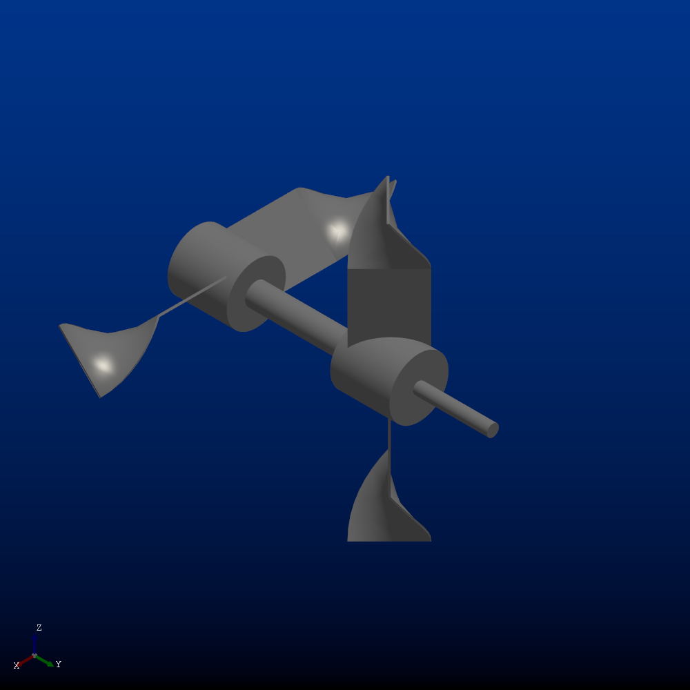
Gas dispersion | Self Aspirating. |

|
Impeller: Glass-lined Series D
Description |
Geometry |
|---|---|
Trapezoidal | Glass-lined trapzoidal impeller. |

|
Hydrofoil | Glass-lined hydrofoil impeller. |

|
Hydrofoil 2 | Glass-lined hydrofoil. Axial flow mixing applications in glass-lined reactors. |

|
Impeller | Retreat-like glass lined impeller. |
|
Frame | Glass-lined frame impeller. |

|
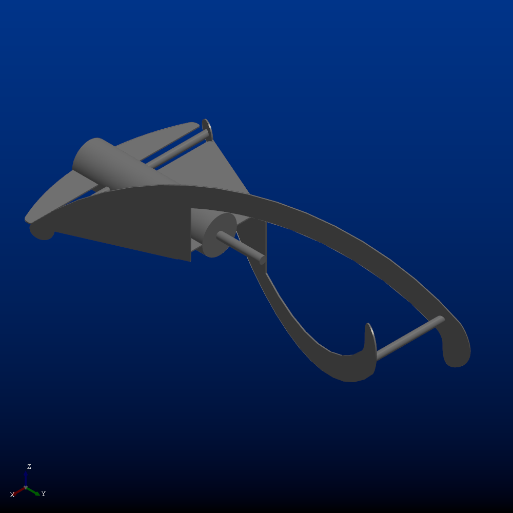
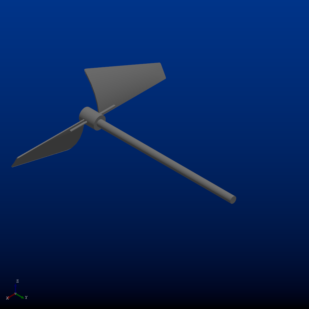
Anchor | Glass-lined anchor impeller. |

|
Turbine | Glass-lined turbine. |

|
Impeller: Glass-lined Series P
Description |
Geometry |
|---|---|
ANC | |

|
GST | |
|
TBF | |

|
CBR | |

|
RCI | |
|
RBT | |
|
PBT | |

|
MSG | |

|
FBT | |

|
TBX | |

|
FDT | |

|
CBT | |
|
MXT | |

|
Impeller: High Efficiency
Description |
Geometry |
|---|---|
High Efficiency Impeller 1 | Turbulent flow blending applications and solids suspension. |

|
High Efficiency Impeller 2 | Turbulent flow blending applications and solids suspension. |
|
High Efficiency Impeller 3 | Turbulent flow blending applications and solids suspension. |

|
Impeller: High Shear
Description |
Geometry |
|---|---|
Sawtooth (high tooth count) | High shear applications. |

|
Sawtooth | High shear applications. |

|
Impeller: High Solidity
Description |
Geometry |
|---|---|
Draft Tube Impeller 2 | Turbulent up-pumping mixing applications. |
|
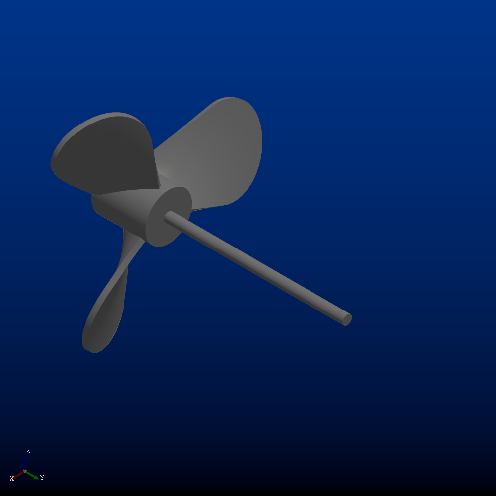
Marine Impeller | High impeller speed, high pumping applications. |
|
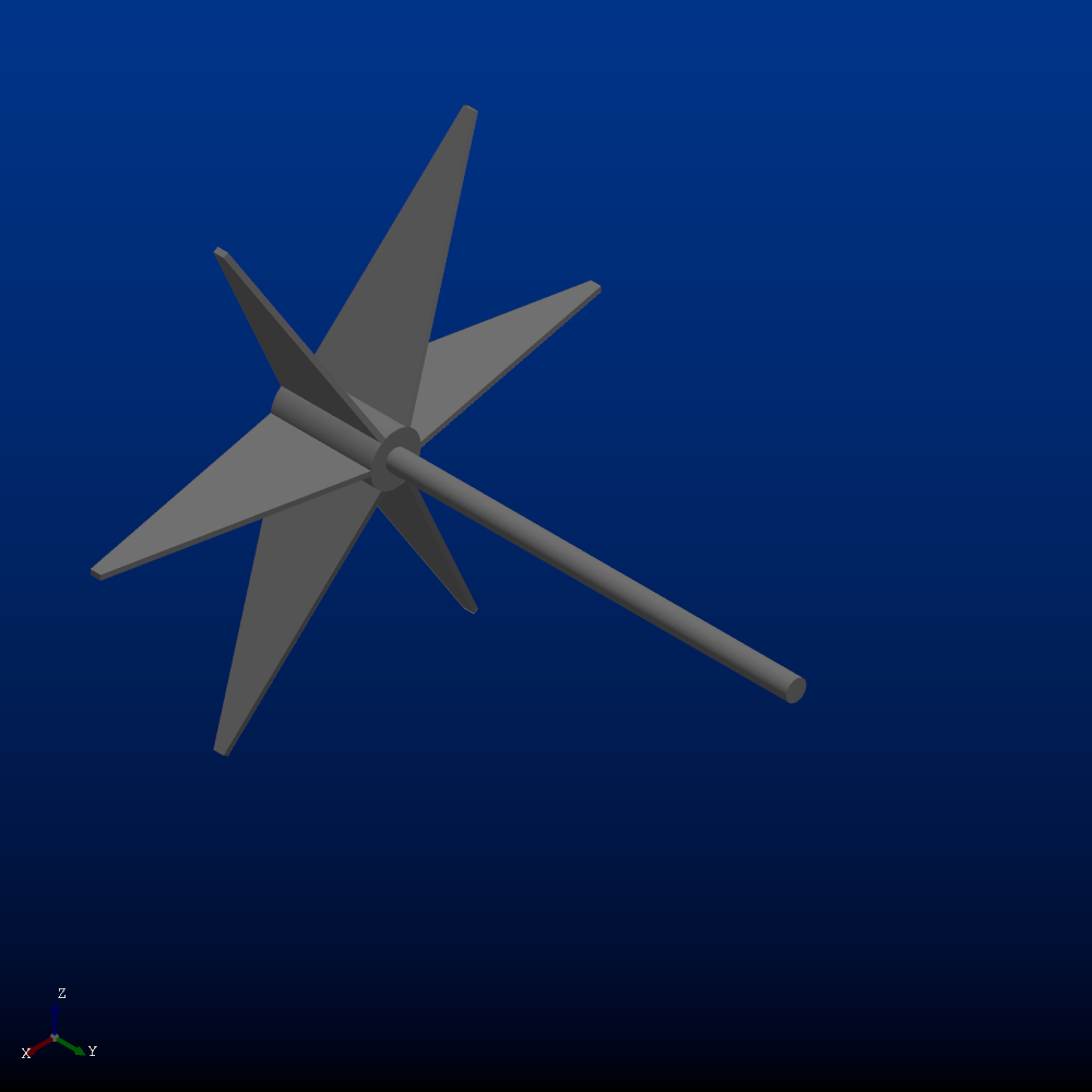
Hydrofoil | Axial flow impeller. |

|
Side Entry Impeller | |

|
Draft Tube Impeller 1 | |

|
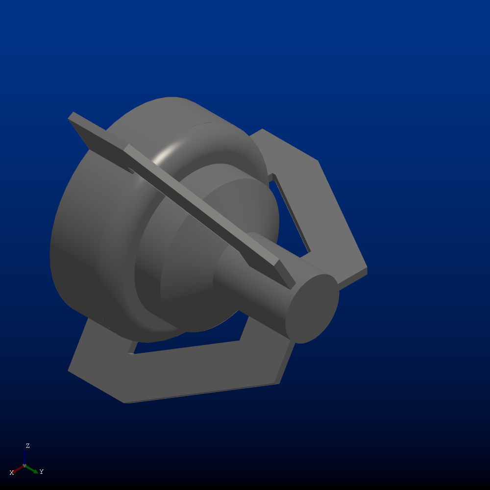
Split Disc | Pharmaceutical and biotechnology blending applications. |

|
Impeller: High Viscosity
Description |
Geometry |
|---|---|
Anchor Impeller | High viscosity blending applications. |

|
High Viscosity Impeller 1 | High viscosity blending applications. |
|
High Viscosity Impeller 2 | High viscosity blending applications. |

|
High Viscosity Impeller 3 | High viscosity blending applications. |

|
High Viscosity Impeller 4 | High viscosity blending applications. |
|
High Viscosity 2 Blade | High viscosity blending applications. |
|
High Viscosity 3 Blade | High viscosity blending applications. |

|
High Viscosity 4 Blade | High viscosity blending applications. |

|
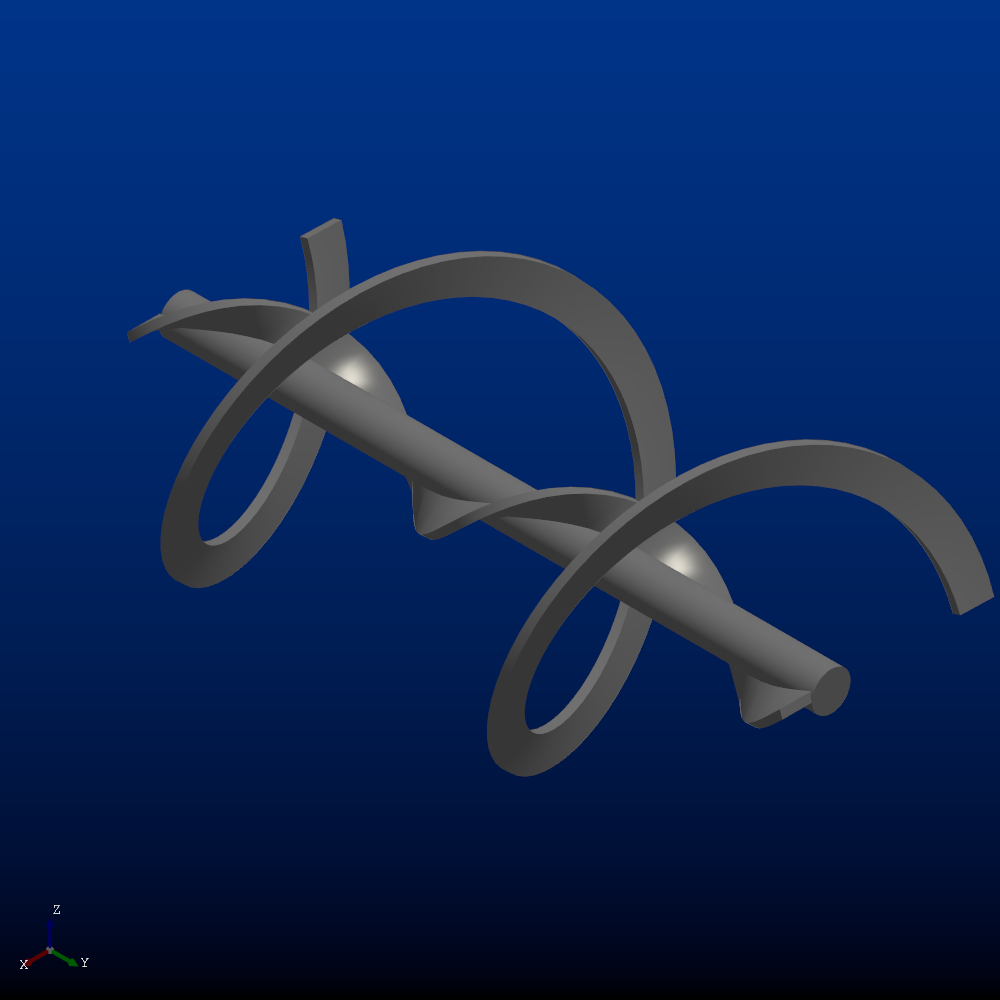
Single Helical Ribbon with Screw | High viscosity blending applications. |
|
Double Helical Ribbon | High viscosity blending applications. |

|
Impeller: Solid Suspension
Description |
Geometry |
|---|---|
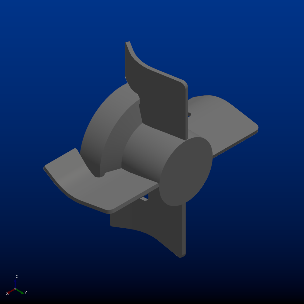
Solid Suspension 4 | |

|
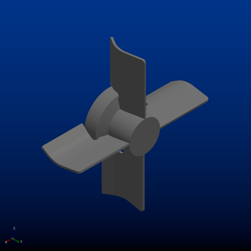
Solid Suspension 2 | |

|
Solid Suspension Impeller 1 | Mass transfer and gas bubble dispersion applications. |

|
High Solidity Hydrofoil | Transitional flow blending and/or high concentration solids suspension applications. |

|
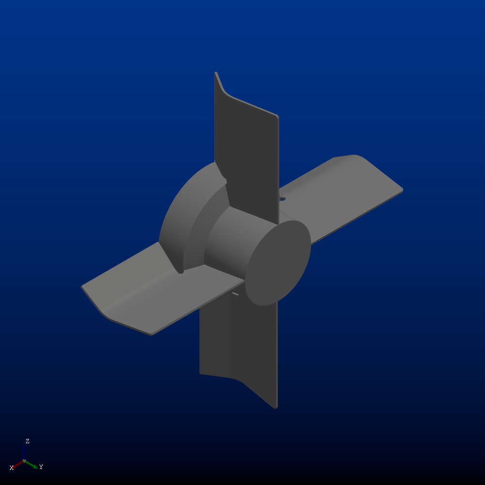
Solid Suspension 3 | |

|
Solid Suspension 3 | |

|
Low Level Mixing | Slurry blending and suspension applications. |

|
Impeller: Transitional flow
Description |
Geometry |
|---|---|
Transitional Flow 2 Blade 25 degrees | |
|
Transitional flow 4 Blade 53 degrees | |

|
Transitional Flow 2 Blade 53 degrees | |

|
Transitional Flow 3 Blade 53 degrees | |

|
Transitional Flow 4 Blade 25 degrees | Higher efficient extension of pitch blade impeller. |

|
Transitional Flow Impeller 1 | Transitional flow. Non-Newtonian/high viscosity blending applications. |
|
Transitional Flow Impeller 2 | Two-fluid transitional flow and/or non-Newtonian blending applications. |

|
Transitional Flow 3 Blade 25 degrees | |

|