 Inlet/Outlet Setup
Introduction
Inlets and outlets are openings in the geometry through which fluid, particles, species, and energy may enter or exit a system.
When you want to define a new inlet or outlet, use the Create menu to select Static Inlet/Outlet. The Inlet/Outlet Setup form will open automatically in the property grid.
Note that static inlets and outlets must be defined on a static geometry and exist along the interface of the flood fill volume. The static boundary condition cannot be exposed to the fluid domain on both sides, the flood fill must only touch one side.
Access
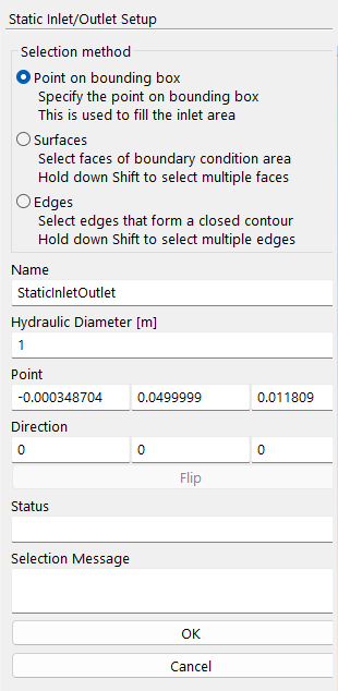
When you select Inlet/Outlet Setup on the Static Inlet/Outlet context-specific toolbar, the form below will launch.
Inlet/Outlet Setup Form
Inlet and outlet boundary conditions are defined along two-dimensional surfaces. These surfaces are characterized by the solid geometry. They can be defined by (1) selecting an existing surface; (2) selecting the edges and allowing a two-dimensional flood fill to construct a surface; or (3) selecting a point on the bounding box where a pipe or hole connects with the bounding box wall and allowing a two-dimensional flood fill to define that space and create a surface.
For a tutorial illustrating all three methods, see selecting surfaces for boundary conditions.
Selection Method
- ○ Point on Bounding Box
Users may choose a point along one of the six sides of the bounding box where a pipe or hole intersects with the bounding box wall; furthermore, users should design their models such that their geometry inlets and outlets are hollow and extend to the bounding box wall. The point does not need to be precisely centered inside the opening, but the point does need to be a “wet” point. At runtime, the code will perform a two-dimensional flood fill using that point as an origin to fill the region enclosed by the intersection of the geometry and the bounding box. This is particularly useful for complicated CAD geometries.
- ○ Surfaces
Users may select any number of existing surfaces and designate them as inlets or outlets. The Surface Mode Setup window will prompt the user to select which geometry contains the desired surface. Multiple segments can be selected sequentially or as a group (using a mouse lasso). This surface then functions as an inlet or outlet at runtime.
In the example below, the surface of a cone is used to function as an inlet:
- ○ Edges
Users may select any number of connected edges along a solid geometry to construct a new surface. The Edge Mode Setup window will prompt the user to select which geometry to query for edges in order to create the desired surface. Multiple segments can be selected sequentially or as a group (using a mouse lasso). When a manifold curve is defined, the GUI automatically fills the enclosed edges with a solid surface representing the extent of the boundary. This surface then functions as an inlet or outlet at runtime.
In the example below, the edge of a pipe is used to define the boundary condition surface. Note that the direction of flow can be flipped:

Here is the inlet defined above after simulation is complete, as seen in M-Star Post:
Important
Users should allocate at least 10 lattice points to inlets and outlets.
A disagreement between the total mass flow into a system and total mass flow out of a system (e.g., a violation of mass conservation) is often due to excessively large Courant numbers.
- Name
Default name for the inlet or outlet. This can be modified by the user.
Point
Using coordinates, the seed point describes either the location of the centroid of the selected surface or the user-defined point selected via the Point on Bounding Box option. The seed point is used for the 2D flood fill.
- X=
X coordinate of the seed point.
- Y=
Y coordinate of the seed point.
- Z=
Z coordinate of the seed point.
Direction
Describes the normal vector of the surface. The X, Y, Z coordinates assign a direction to the flow; positive is fluid entering the system and negative is fluid leaving the system.
- X=
X coordinate of the flow direction.
- Y=
Y coordinate of the flow direction.
- Z=
Z coordinate of the flow direction.
- Flip Direction
This button is a convenience feature to flip the direction of the boundary condition.
Diagnostics
- Status
Informs the user when they have successfully selected a manifold surface.
- Hydraulic Diameter
m | Used to compute the Reynolds number, Courant number, and time step during pre-processing. If the Poiseuille boundary condition is used, this value controls the velocity profile. For cylindrical pipes, the hydraulic diameter is inside the diameter of the pipes. For other geometries, it is equal to 4 times the area, divided by the perimeter. For the Point on Bounding Box, the hydraulic diameter is not computed automatically but can be user set.
- Selection Message
Gives a report about the boundary condition. ‘Non-axis aligned’ means that the boundary condition is not aligned with the lattice. ‘Axis aligned’ means that the boundary condition is aligned with the lattice.
Note
In general, ‘Axis aligned’ conditions are more stable. If possible, efforts should be made to make boundary conditions on lattice. For a tutorial on optimizing stability, see On and Off Lattice Boundary Conditions.
- Cancel
This button cancels changes to the inlet or outlet and closes the form.
- OK
This button accepts changes to the inlet or outlet and closes the form.
Location
The Inlet/Outlet Setup form is found on the following context-specific toolbars (accessed through the Create menu):
