Model Setup
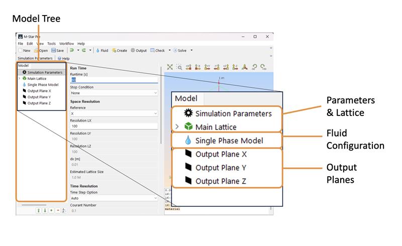
Every model in M-Star CFD requires three absolutes: a Simulation Parameters component, a Main Lattice component, and a Fluid Configuration. By default, we add optional Output Planes. You can add more components to the model via the Create icon.
Simulation Parameters: This controls resolution time step and initial fluid states.
Main Lattice: This domain defines the extent of the model universe and contains all physics.
Fluid Configuration: This component defines your fluid configuration. The default configuration is Single Phase.
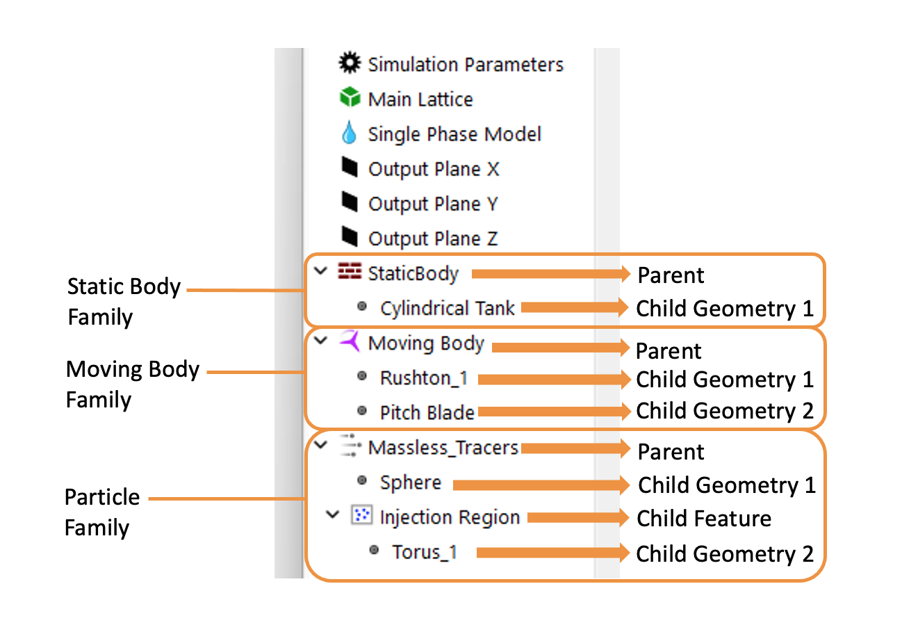
Parent-Child Relationship
The parent-child relationship is a foundational concept used to structure simulations in M-Star CFD. This hierarchical approach allows users to define global properties at the parent level and apply these properties to specific regions or geometries through child components. Parents and children together form object families. In the model tree, parent definitions appear as top-level entries. Child geometry, derived from these definitions, are shown as indented nodes to indicate dependency and hierarchy.
Parents serve as containers for behaviors within a simulation. They define overarching characteristics.
Static and Moving Bodies: Global properties and boundary conditions assigned to a set of children
Scalar Fields: Overall properties like diffusion coefficients, advection schemes, and scalar field densities
Particles: Attributes including particle density, size distribution, forces, and interaction mechanics
Importantly, parent components do not possess physical form until associated with child geometries. Parents therefore act as templates or blueprints, outlining how certain properties or behaviors should manifest within the simulation. New parents can be added to the model tree via the Create menu.
Children are representations defining where the properties defined by their parents are applied. They specify the shape, extent, and location within the simulation domain.
Geometry Definition: Defines the physical shape and extent of static boundaries, moving impellers, or regions where species are introduced
Property Application: Determines where and how the parent’s properties—like scalar concentrations or particle injections—are applied within the simulation
Children geometry can be added to parents by importing CAD files or selecting from geometry catalogs.
Existing parents and children (object families, see above) can be duplicated, copied, and swapped between families using the Edit command. Parent and child geometry can be renamed by clicking the right mouse button.
Note
For particles and scalar parents, intermediate components may be nested within the parent-child hierarchy. These intermediate particle injection zones and scalar injection zones are used to customize the injection behavior of specific child geometry. When available, these child features can be added to the parents via context-specific tool bars.