Parametric Impellers
These are the parameters that define the child geometry. The categories, settings, and/or selections available within the property grid depend on the child geometry type, as listed in the catalog.
Property Grid
General
- Location
This parameter defines the position of the geometry mount point within the domain. Editing this value adjusts the location of the geometry within the domain.
If an object is selected from the Parametric Primitives group, the following setting will launch.
- Primitive Type
This parameter defines how the primative geometry is filled. Two options are available: shell and solid. These options inform the behavior of the Trim command.
- Shell
This defines the primitive as a zero-thickness surface.
- Solid
This defines the primitive as a filled solid object.
Shape Parameters
These are the parameters that define the child geometry. The exposed parameters will depend on the geometry type, as listed below.
Catalog
Anchor Impeller
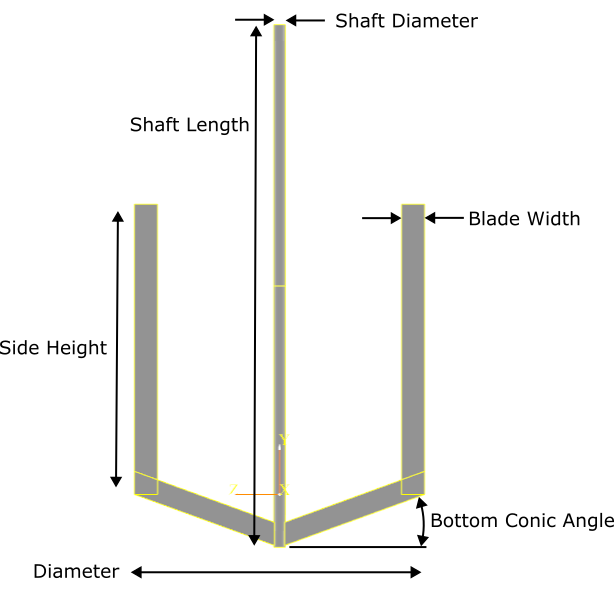
- Location
Object position
- Diameter
Diameter of impeller
- Side Height
Length of vertical blade
- Bottom Conic Angle
Angle of bottom blades connected to shaft
- Blade Width
Width of blades
- Blade Thickness
Thickness of blades
- Shaft Diameter
Shaft diameter
- Shaft Length
Shaft length
Counter Flow
The counter flow impeller is composed of three parts:
Part 1 : Trapezoid blade part connected to shaft
Part 2 : Rectangle blade part connected to part 1. A vertical square connected to this part is dimensioned based on the Part 2 width
Shaft
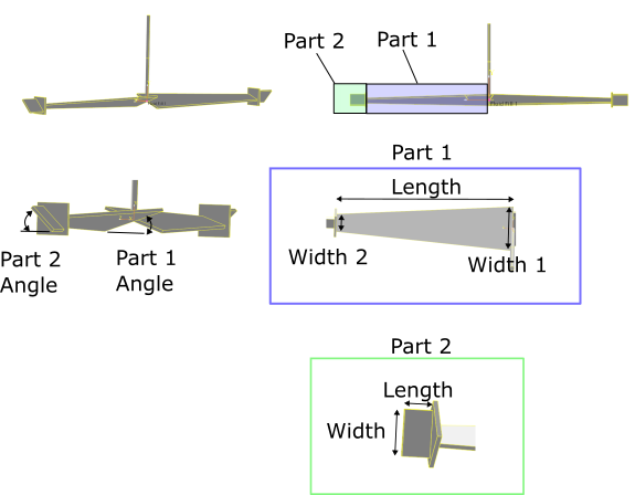
- Number Blades
Number of blades
- Thickness
Thickness of blade solids
- Part 1 Angle
Angle of part 1 of blade
- Part 1 Length
Length of part 1 trapezoid
- Part 1 Width 1
Base width of part 1 trapezoid
- Part 1 Width 2
Tip width of part 1 trapezoid
- Part 2 Length
Length of part 2 rectangle
- Part 2 Width
Width of part 2 rectangle
- Part 2 Angle
Angle of part 2
- Shaft Diameter
Shaft diameter
- Shaft Length
Shaft length
Helical Ribbon
The helical ribbon is a rectangle that is extruded along a helical path. The rectangle dimensions are controled by Blade Width and Thickness. The helix parameters are also available.
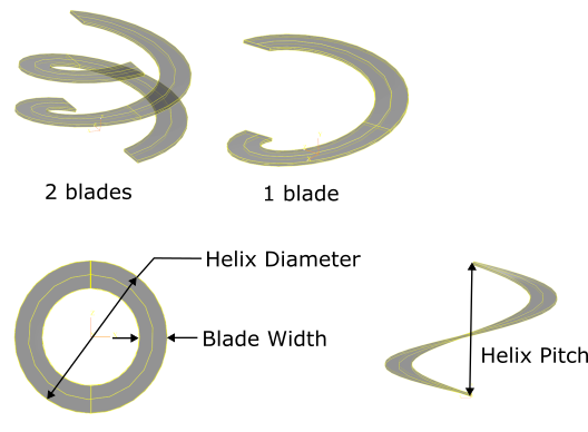
- Number Blades
Number of blades
- Number of Turns
Number of helix turns. May be a fractional value.
- Blade Width
Width of blade
- Helix Pitch
Height of helix for every 1 turn
- Helix Diameter
Diamter of helix
- Thickness
Thickness of blade
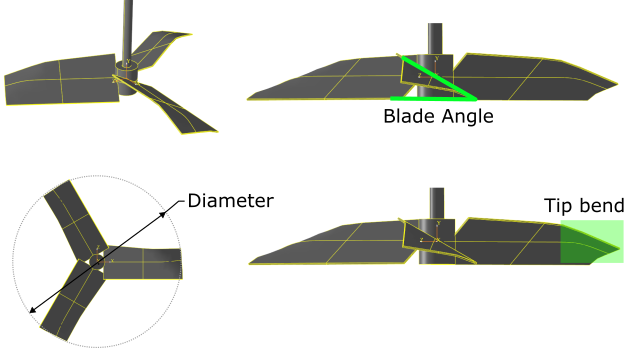
High Solidity Hydrofoil (HSH)
This impeller represents a notional high solidity hydrofoil with large blades. The leading edge tip of each blade is bent slightly.
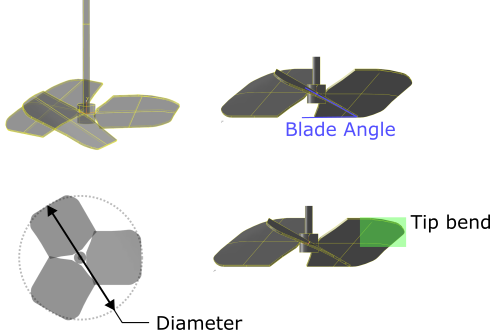
- Number Blades
Number of impeller blades
- Diameter
Diameter [Model Units]
- Shaft Length
Shaft length. Set to zero to disable [Model Units]
- Shaft Diameter
Shaft diameter [Model Units]
- Blade Angle
Blade angle
Low Solidity Hydrofoil (LSH)
This impeller represents a notional low solidity hydrofoil. The leading edge tip of each blade is bent slightly.
- Number Blades
Number of hydrofoil impeller blades
- Diameter
Diameter of the hydrofoil impeller [Model Units]
- Shaft Length
Shaft length. Set to zero to disable [Model Units]
- Shaft Diameter
Shaft diameter [Model Units]
- Blade Angle
Hydrofoil Blade angle [deg]
Pitch Blade
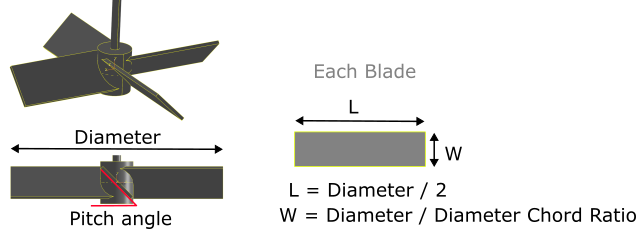
- Number Blades
Number of impeller blades
- Diameter
Diameter of impeller. The length of each blade is Diameter / 2.
- Thickness
Thickness of blades
- Pitch Angle
Blade angle [deg]
- Diameter Chord Ratio
The diameter of the impeller divided by the width of the blade. Controls the aspect ratio.
- Shaft Length
Shaft length. Set to zero to disable
- Shaft Diameter
Shaft diameter
Retreat
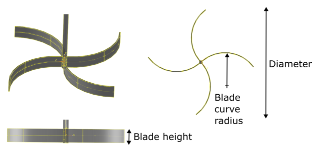
- Diameter
Diameter
- Number Blades
Number of blades
- Hub Diameter
Hub diameter
- Blade curve radius
Radius of blade curve
- Blade height
Blade height
- Blade Thickness
Blade thickness
- Shaft Length
Shaft length. Set to zero to disable
- Shaft Diameter
Shaft diameter
Rushton
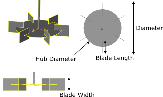
- Rushton Parameters
Auto: Default rushton dimensions
Specified: Customize the geometry dimensions
- Diameter
Diameter
- N Blades
Number of impeller blades
- Blade Length
Blade length
- Blade Width
W
- Thickness
Solids thickness
- Hub Diameter
Diameter of flat hub
- Shaft Length
Shaft length. Set to zero to disable
- Shaft Diameter
Shaft diameter
Sawtooth
This impeller is built using a flat circular disk as the hub, with “teeth” around the perimeter of the hub. Each tooth starts out as a flat rectangular surface with a length equal to “Tooth Length” and width based on the number of teeth around the circumference of the hub. The tooth is then rotated about one of its corners by the angle Blade Angle, then a bend is applied. The blade angle controls the oblique bend angle for each tooth. The tooth is then joined with the hub.
- Diameter
Diameter [Model Units]
- Number Teeth
Number of teeth
- Blade Angle
Blade Angle. Determines oblique bend angle of each tooth. As values approach zero, no bend will be realized [deg]
- Tooth Length
Length of each tooth
- Shaft Length
Shaft length. Set to zero to disable [Model Units]
- Shaft Diameter
Shaft diameter [Model Units]
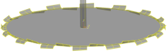
Side Scraper
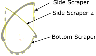
Fig. 49 Side scraper parts
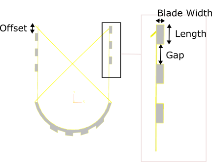
Fig. 50 Side scraper
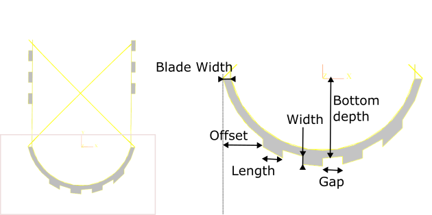
Fig. 51 Bottom scraper
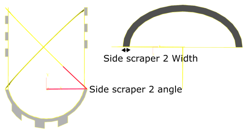
Fig. 52 Side scraper 2
- Diameter
Outer diameter of impeller
- Side Height
See diagram
- Bottom Depth
See diagram
- Blade Thickness
See diagram
- Side Scraper Number
See diagram
- Side Scraper Blade Width
See diagram
- Side Scraper Length
See diagram
- Side Scraper Gap
See diagram
- Side Scraper Offset
See diagram
- Bottom Scraper Number
See diagram
- Bottom Scraper Blade Width
See diagram
- Bottom Scraper Offset
See diagram
- Bottom Scraper Length
See diagram
- Bottom Scraper Width
See diagram
- Bottom Scraper Gap
See diagram
- Side Scraper 2 Blade Width
See diagram
- Side Scraper 2 Angle
See diagram
Split Disc
- Diameter
Outer diameter
- Thickness
Blade thickness
- Number Blades
Number of blades
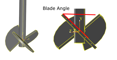
- Blade Angle
See diagram
- Shaft length
Shaft length
- Shaft Diameter
Shaft length