 Add Fill Point
Introduction
M-Star CFD uses a 3D flood fill algorithm to generate region tags over the lattice at runtime. Each fill point defines the origin of a volumetric expansion that marks all reachable voxels until blocked by static geometry or the simulation bounding box. The resulting tagged regions are central to several workflows, including defining the active region stored in memory, initializing disconnected regions with different fluids, scoping global variable reductions, and defining particle or scalar injection locations.
After defining static and moving bodies (whether single part or multiple components), fill points are placed to seed the flood fills. These points should be in the bulk fluid away from any static or moving body geometry. At time zero, the solver expands from each fill point until reaching static boundaries or the bounding box, tagging connected regions and distinguishing them from disconnected ones. This approach automatically decomposes the system geometry into distinct regions, without manual preprocessing. Conceptually, the 3D flood fill behaves like an expanding balloon: it grows outward from the fill point, conforming to the geometry and stopping at boundaries. Because this decomposition happens algorithmically at runtime, there is no need to import separate geometries, construct region masks, or duplicate models.
Note
The flood fill point is shown in the 3D view. In most cases, the default flood fill location (Domain Center) is acceptable.
In some cases however, such as U-tube manometers, toroidal geometries, or tanks with interior support structures, the point must be relocated to a location interior to the vessel.
For all simulations, the interior volume calculated during the flood fill routine is reported to the simulation output log. If this calculated volume is in significant disagreement with the expected tank volume, check the flood fill point.
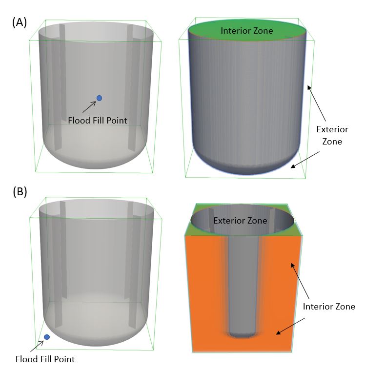
To illustrate the effect of flood fill seed location, consider the two flood fill results below. In image (A), the flood fill point was located inside the vessel in a region that is known to contain fluid during the simulation. Appropriately, the active region of the lattice domain is inside the tank, while the inactive region is outside the tank.
In image (B), the flood fill point was inappropriately located outside the vessel. The active region of the lattice domain is inappropriately located outside the tank, while the inactive region is inside the tank.
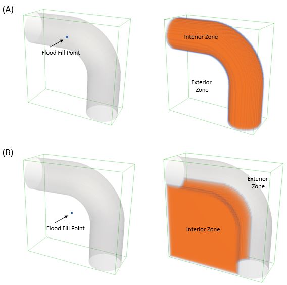
Further illustration is presented below, for a system involving flow around a bend. In image (A), the flood fill point is located inside the pipe. The flood fill algorithm expands to the sidewalls of the pipe and the lattice bounding box. The interior zone is (correctly) inside the pipe elbow. The exterior zone is (correctly) located outside the elbow. Regions in the active zone will be modeled. Those in the inactive zone will not be modeled.
In image (B), the flood fill point is located outside the pipe. The flood fill algorithm again expands to the sidewalls of the pipe and the lattice bounding box. The interior zone is incorrectly located outside the pipe. The flood fill point needs to be located inside the pipe on order to make the inside of the pipe the active zone.
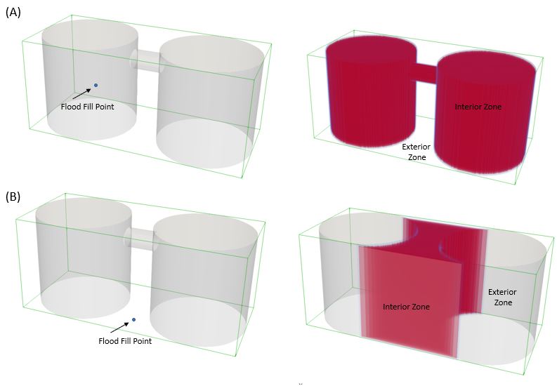
A final illustration is presented below. In this example, we model species transport between two tanks connected by a small pipe. In image (B), improper selection of the point leads to improper active versus inactive zones.
Important
The results of the flood fill algorithm are recorded in the
BoundaryConditions.txtfile, which can be rendered in M-Star Post under the Volume Fraction option. Regions where the reported fluid value is equal to 0 are inactive simulation zones which were untouched by the flood fill.Simulations predicting non-physical forces on moving objects (e.g., giganewtons) and/or zero fluid velocity despite the presence of a momentum source often result from an improper flood fill point location.
If most of the simulation zone is inactive, consider using a sparse mesh to improve runtime speed and decrease memory requirements.
Fill Points on the Main Lattice
The Fill Point on the main lattice is required for every simulation. When a fill point is added under the Main Lattice, the resulting tagged region defines the active portion of the domain — the set of lattice voxels that are allocated in memory and included in physics calculations. The 3D flood fill is performed once at time zero. Voxels inside the tagged region are active; voxels outside are excluded entirely and have no impact on the simulation. This distinction between active and inactive zones is fundamental for both solver performance and physical correctness. Because the flood fill point under the Main Lattice determines what is stored and solved, it is critical to verify that the tagged region correctly represents the intended interior volumes of the system.
Access
When you select Add Fill Point on the applicable context-specific toolbar, a new fill point is formed and the property grid below will launch.
Property Grid
General
- Point
m | This is where the location for the fill point is indicated. The location can be moved or modified by adjusting the coordinates. The point can also be moved or rotated by using Move and Recenter on the Fill Point Toolbar.
Location
The Add Fill Point form is found on the following context-specific toolbars:

Fill Point Output Data
Fill points do not introduce any new files or output streams. They are used internally to generate region tags across the lattice.
Fill Point Toolbar
Context-Specific Toolbar Options |
Description |
|---|---|
|
The Move form enables three-dimensional rigid body transform of object through free drag or point-to-point snapping. |
|
The Recenter command snaps a plane to the center of the bounding box. |
|
The Help command launches the M-Star reference documentation in your web browser. |
 Recenter
 Help
HelpSee also Child Geometry Context Specific Toolbar.
For a full description of each selection on the Context-Specific Toolbar, see Toolbar Selections.