 Moving Inlet/Outlet
Introduction
Moving inlets and outlets are boundary conditions through which fluid, particles, species, and energy may enter or exit a system. The fluid entering the system through an inlet can contain a user-defined temperature, user-defined species concentrations, solid particle densities, and bubble volume fractions. Examples of systems with moving inlets and outlets include moving nozzles, filling systems, and moving vents.
Moving inlets and outlets are defined as circular boundary conditions with a user-set diameter. They are not tied to a specific edge or surface, and they may be immersed in the system. However, moving inlets and outlets are limited to a circular shape with user-set fluid velocity.

Download Sample File: Moving Inlet
The geometry of the circular moving inlet or outlet is characterized by its diameter, location, and orientation. Although the diameter remains constant, the location and orientation can evolve in time per user-defined functions. The velocity of the fluid along the boundary condition surface can also evolve in time per a user-defined velocity expression.
Systems may contain multiple boundary conditions. For single-fluid systems, a system with one inlet should contain at least one outlet; since the fluid volume is constant in these systems, inflow must be balanced with outflow. Simulations with filling and draining systems, as modeled using a free surface model, need only one boundary condition. These points are discussed in the Pipe Flow tutorial and the Tanks with Inlets and Outlets tutorial.
Moving inlets and outlets can only be defined for single phase, free surface, and two-fluid immiscible fluid configurations. They cannot be defined for background fluid and no-fluid configurations.
Boundary conditions affixed to a static surface are Static Inlets and Outlets.
Property Grid
General
- Diameter
m | The diameter of the circle defining the geometry of the boundary condition surface in model units.
- Velocity Magnitude UDF
m/s | This UDF defines the velocity along the boundary condition surface. It can be a function of position and the pressure realized at the boundary condition. Positive values move in the direction of the velocity unit vector. Negative values move in the opposite direction of the velocity unit vector. This is a System UDF.
Download Sample File:
Velocity Magnitude- Ramp Time
s | Ramp time for boundary condition.
For constant velocity boundary conditions, this is the interval over which inlet velocity will be increased from zero to the user-defined constant velocity, via a quarter sine wave.
Mathematically speaking, the ramp prevents the system from realizing an infinite acceleration at the boundary condition over the first time step. Physically speaking, the ramp is analogous to the time required to open a value and actuate a pump.
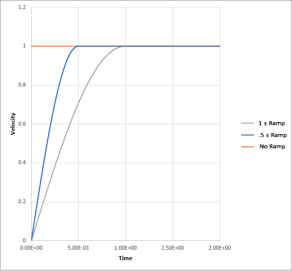
Fig. 61 This graph shows an example of a zero, half-second, and one-second ramp time with a steady-state velocity of one meter per second.
Note
The purpose of the ramp is to limit the propgation of “shock waves” throughout the system, associated with a step-increase in boundary velocity or pressure.
The duration of the ramp time, in terms of time steps, should be comparable to the number of lattice points across the system domain.
Placement
The placement of the moving inlet or outlet is defined by displacement and orientation. Displacement describes the position relative to the initial location and may have positive or negative values. The three components of the displacement vector are defined as UDFs.
Orientation is represented by a three-dimensional unit vector which describes the direction of flow. This vector is always dimensionless and normalized to have a length of 1.0. Individual UDFs are defined for the x, y, and z components of the vector, which is expressed with respect to the system basis vectors. The orientation unit vector is then multiplied by the velocity magnitude UDF to compute the instantaneous flow velocity leaving the boundary.
Download Sample File: Displacement and Orientation UDF
- Location
m | The initial position of the center of the boundary condition surface in model units.
- Displacement X UDF
m | This UDF defines the x-displacement of the mount point about the initial position. Values may be positive or negative. The initial value of the UDF should be zero. This is a System UDF.
- Displacement Y UDF
m | This UDF defines the y-displacement of the mount point about the initial position. Values may be positive or negative. The initial value of the UDF should be zero. This is a System UDF.
- Displacement Z UDF
m | This UDF defines the z-displacement of the mount point about the initial position. Values may be positive or negative. The initial value of the UDF should be zero. This is a System UDF.
- Orientation Unit Vector X UDF
unitless | This vector is defined with respect to the system basis vectors. The vector will be normalized by the solver if the length is not equal to 1. Can be a time-varying expression. This is a System UDF.
- Orientation Unit Vector Y UDF
unitless | This vector is defined with respect to the system basis vectors. The vector will be normalized by the solver if the length is not equal to 1. Can be a time-varying expression. This is a System UDF.
- Orientation Unit Vector Z UDF
unitless | This vector is defined with respect to the system basis vectors. The vector will be normalized by the solver if the length is not equal to 1. Can be a time-varying expression. This is a System UDF.
Advanced
- Duration Option
This defines the time interval over which the inlet or outlet boundary conditions are applied. Throughout the specified duration, transport along the boundary condition surface evolves according to the user-defined parameterization. Outside this duration, the velocity along the boundary condition surface is set to zero. This change is analogous to closing a valve in a system, meaning there is no mass, species, momentum, particle, or thermal transport across the boundary condition surface. This behavior overwrites all user-defined parameters, setting the velocity and fluxes to zero.
- Single Interval
Transport along the boundary condition surface evolves over the duration specified by the start and end time. Outside this interval, the velocity along the boundary condition surface is set to zero.
- Start Time
s | Start time for transport along the boundary condition.
- End Time Option
Two options are available for end time of transport along the boundary condition.
- End of Simulation
End time for transport along the boundary condition corresponds with the end of the simulation time.
- Specified
An end time for transport along the boundary condition is specified.
- End Time
s | End time for transport along the boundary condition. The default is -1 to indicate the end of the simulation.
- Custom Expression
Transport along the boundary condition surface evolves over a custom user-defined expression. When the expression output is set to zero, there is no mass, species, momentum, particle, or thermal transport across the boundary condition surface. When the duration is set to one, the velocity along the boundary condition surface evolves according to the user-defined parameterization.
- Open Close UDF
unitless | This UDF is an expression for the open close condition. An output value greater than zero is interpreted as an open condition, and less than zero is interpreted as a closed condition. This is a System UDF.
- End Time Option
Two options are available for end time of transport along the boundary condition.
- End of Simulation
End time for transport along the boundary condition corresponds with the end of the simulation time.
- Specified
An end time for transport along the boundary condition is specified.
- End Time
s | End time for transport along the boundary condition. The default is -1 to indicate the end of the simulation.
Download Sample File:
Open Close
Display Attributes
- Visible
This controls whether the object is displayed in the 3D viewing panel.
- Hidden
The object is not displayed in the 3D view.
- Shown
The object is displayed in the 3D view.
- Mode
This controls how the object is rendered.
- Wire
This renders the object as a wireframe.
- Color
This sets the color of the wireframe.
- Width
This adjusts the line width used to render the wireframe.
- Shaded
This renders the object as a shaded surface.
- Material
This sets the surface material. Available options are Aluminum, Steel, Chrome, Plastic, and Glass.
- Color
This sets the surface color.
- Opacity
When glass is selected, this sets surface opacity.
Moving Inlet/Outlet Output Data
Moving inlet and outlet output data are written to ASCII text files. Each moving inlet or outlet produces a unique output file with a file name linked to its dynamic name.
The moving inlet/outlet output data are printed to Moving Inlet/Outlet Statistics files. The ASCII .txt files store the time-evolving data of both raw and reduced output variables associated with each moving inlet or outlet. The output data always include fluid pressure, area, mean velocity, volumetric flow rate, and state (flow on versus off). The output data may also include statistics related to scalar fields and the thermal field, when appropriate. These text files are updated and appended at the Statistics Write Interval. A full preview and description of the data written to each moving inlet or outlet output file is available in the Statistics Output Data preview panel.
Moving Inlet/Outlet Toolbar
Context-Specific Toolbar Forms |
Description |
|---|---|
|
The Move form enables three-dimensional rigid body transform of object through free drag or point-to-point snapping. |
|
The Help command launches the M-Star reference documentation in your web browser. |
 Help
HelpFor a full description of each option, see Context-Specific Toolbar selections.