Explode Geometry Form

The explode geometry form decomposes a CAD geometry into its constituent solid surfaces. The explode geometry capability can break up these compounds into their child objects.

Exploding Geometry Workflow

The following example uses the file sampleTank_step203.STEP, if you want to reproduce these steps yourself.

  1. Go to Create>Static Body; select the STEP file to import as is.

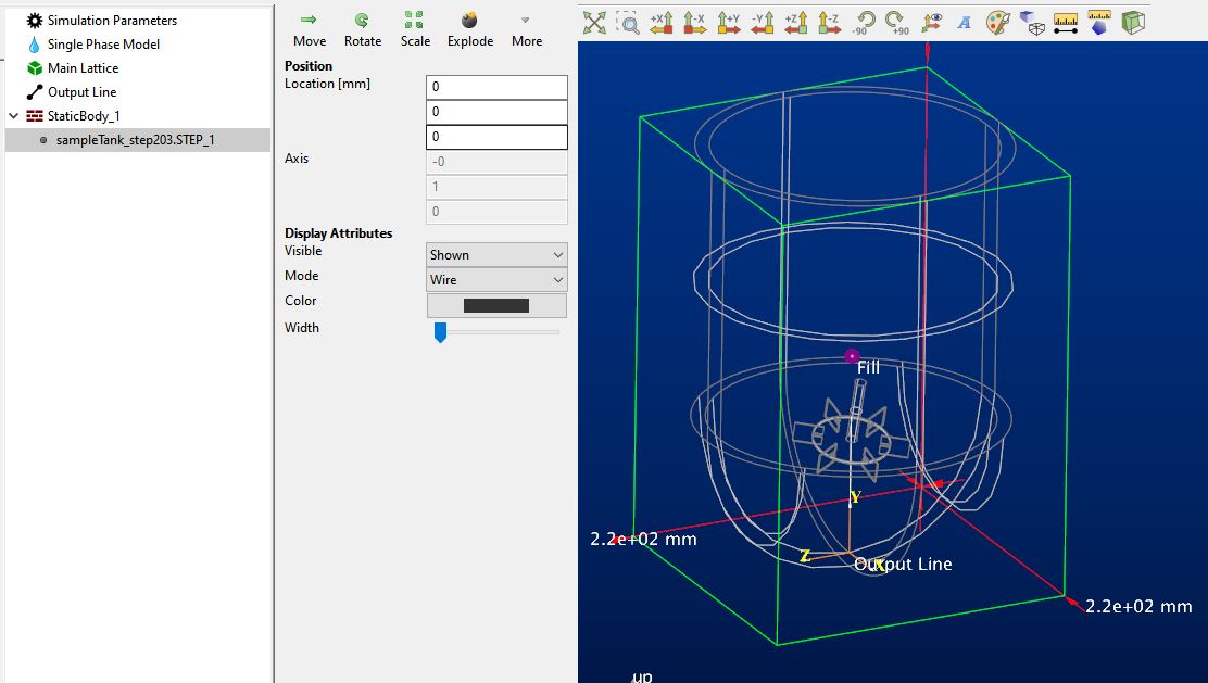
    The model initially looks like this. Note that the impeller and tank are in the same file, but they come in as one piece of geometry.

    ../../../_images/explode_1.JPG
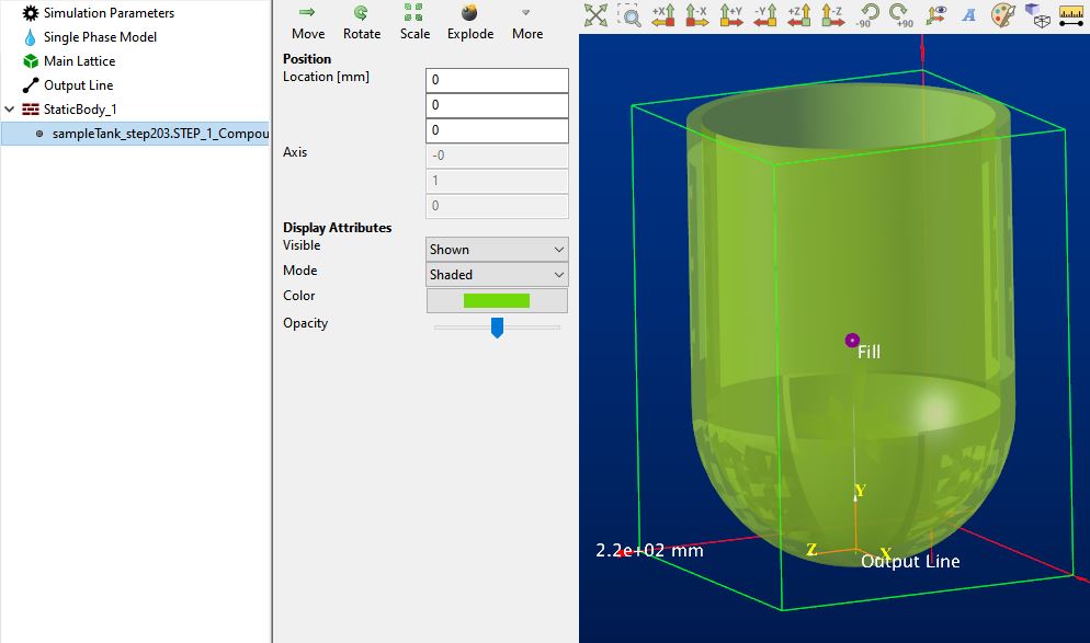
  2. Select the new child geometry and click Explode. This brings up a form that shows the number of new objects that will be created.

  3. Select the “Delete original object” (and unselect “Use random colors for new objects”) and click OK. The new model looks like this.

    ../../../_images/explode_2.JPG
  4. Next, apply the explode action again to the child. On the form, two solid objects will be created. Enable the delete original object and click OK.

    ../../../_images/explode_3.JPG

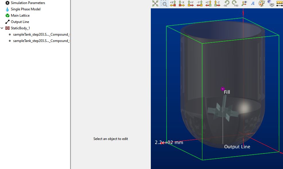
You can see two new child solid objects are now under the static body. At this point you can delete, copy, or move the individual child geometries as needed.

If you want to move the impeller geometry to a different parent type:

  1. Select Create > Moving Body. Skip the addition of child geometry; it is already present in our model.

  2. Right click on the impeller child geometry, select Cut.

  3. Select the Moving Body parent, right click, and select Paste. The geometry will be moved to the moving body.

  4. We still need to define the moving body axis, so select the moving body and use the Define Axis action. Use the edges to define the axis center and direction, then click OK.

Assembly Object Trees

Some geometry imported from CAD can be exploded into multiple geometries. STEP and IGES files can contain assemblies of objects. These assemblies are typically represented as a tree of objects inside the file. In the context of M-Star, we refer to these types of objects as “Compound” or “Solid Compound.” These compound objects may contain one or more sub-objects. The explode geometry capability can break up these compounds into their child objects.

Tip

You can use the Import CAD Assembly Workflow tool to break up geometries in a more streamlined workflow.

For example, if we have a CAD file with a compound that contains two solid objects, the assembly/tree might look like this:

  • Compound 1
    • Solid 1

    • Solid 2

If we explode this geometry, we will break apart the Compound 1 object into two new objects, Solid 1 and Solid 2. After exploding, we would end up with:

  • Solid 1

  • Solid 2

In other cases you may have multiple levels of compounds. For example, the following tree is valid:

  • Compound 1
    • Compound 2
      • Solid 1

      • Solid 2

If we applied an explode operation to this geometry, we would get:

  • Compound 2
    • Solid 1

    • Solid 2

If we applied another explode operation to this geometry, we would get:

  • Solid 1

  • Solid 2

Sometimes multiple explosions are necessary to get at the individual solids.

Location

The Explode Geometry form is found on the following context-specific toolbars (accessed through the Create menu):