 Static Body
Introduction
Static bodies represent walls and boundaries within the simulation. They confine fluid and particles, define the extents of the main lattice, and act as boundaries for scalar and thermal fields, making them a foundational element of most simulations. Static bodies can also be used to evaluate custom variables along their surfaces and to apply reactions to scalar fields at the boundary. All static body parents require at least one child geometry, which is added to the parent using the Add Geometry command found on the Context Specific Toolbar.
Positioning Static Bodies
Parent
Once you have imported a static body, select the parent static geometry in the model tree. Then select the type of transformation (move, rotate, scale, etc.) from the Static Body Toolbar. A transformation to the parent affects all children. The position and orientation of the parent (relative to the simulation basis) is reported in the property grid.
Children
Children can be rotated, translated, scaled, and colored independently of any parents and siblings. The position and orientation of the child (relative to the simulation frame) is reported in the property grid. The position of all children is defined relative to the global origin.
See Importing CAD geometry tutorial.
Property Grid
General
- Boundary Type
Static bodies can be modeled using either a grid aligned, on-lattice voxelized approach or an off-lattice interpolated approach. With increasing resolution, the difference between these two approaches diminishes.
- Grid Aligned
In the on-lattice voxelized approach, any fluid lattice element that intersects the static geometry is assigned a no-slip, bounce-back wall boundary condition. This approach is ideal for flat, lattice-aligned walls. Any curved surfaces, however, will follow a stair-step contour with a step height equal to the local lattice spacing.
- On-Wall Velocity
This is the surface velocity of the static body. Per the no-slip boundary condition, the fluid will have zero velocity relative to the boundary. Most static bodies have no surface velocity.
- Off
Wall velocity is set to zero. The no-slip boundary condition demands that the fluid velocity at the wall also be zero.
- Translation
User-defined translational expression for the wall velocity. This can be useful for defining a static surface with non-zero translational wall velocity, such as conveying surfaces. When the translation setting is on, three selections be
- Translation Velocity X UDF
m/s | User-defined expression for the X-component of the solid surface velocity. Pressing the Edit button launches the UDF editor which can be used to define the velocity. This is a System UDF.
- Translation Velocity Y UDF
m/s | User-defined expression for the Y-component of the solid surface velocity. Pressing the Edit button launches the UDF editor which can be used to define the velocity. This is a System UDF.
- Translation Velocity Z UDF
m/s | User-defined expression for the Z-component of the solid surface velocity. Pressing the Edit button launches the UDF editor which can be used to define the velocity. This is a System UDF.
Download Sample File:
Translation Velocity- Rotation
User-defined rotational expression for the wall velocity. This can be useful for defining a static surface with non-zero azimuthal wall velocity, such as a spinning drum.
- Rotation Point
m | User defined location of the rotation axis mount point.
- Rotation Axis
User defined unit vector describing the axis of rotation. The root of this vector is the axis point.
- Rotation Speed UDF
rpm | This UDF defines the time-evolution of the rotational speed about the (fixed) rotation axis. Values may be positive or negative. The direction of rotation is indicated by the arrow drawn around the rotation axis in the viewing panel. This is a System UDF.
Download Sample File:
Rotation Speed- Interpolated
For the off-lattice interpolated approach, fluid lattice elements are not explicitly redefined. Rather, the effects of the wall on the fluid are extrapolated onto the fluid as a function of distance from the wall. For curved or non–grid-aligned surfaces, the off-lattice interpolated approach can provide a superior representation of the boundary.
- Wall Function
When the wall function option is enabled, the solver will apply a velocity boundary condition at the wall based on the classic velocity profile for turbulent boundary layers. As a result, lower resolution is required while still modeling the turbulent boundary layer. Turbulent boundary layers exhibit steep velocity gradients near the wall. As a result, explicitly resolving the turbulent boundary layer for a high Reynolds number flow using a Navier-Stokes solution is typically impractical due to the high resolution required. Wall functions are used to address this challenge by applying wall boundary conditions in a way that accounts for the expected near wall behavior. Keep in mind that the accuracy of this approach is limited by how applicable the pre-determined velocity profile is to a specific application.
The wall function is solved locally at each grid point adjacent to the static body surface. First, the friction velocity is calculated based on the local fluid velocity (using Equation 20 in this article). Next, the velocity boundary condition is calculated using the Musker profile (found here). This approach works seamlessly across the viscous sublayer, buffer layer, and inertial layer.
- Wall Roughness
m | When the wall function is enabled, a wall roughness parameter can also be applied where the wall roughness is the characteristic height of the surface fluctuations (using Equation 7). A value of zero signifies a smooth wall.
If a free surface or immiscible two fluid model is selected, the following section will launch:
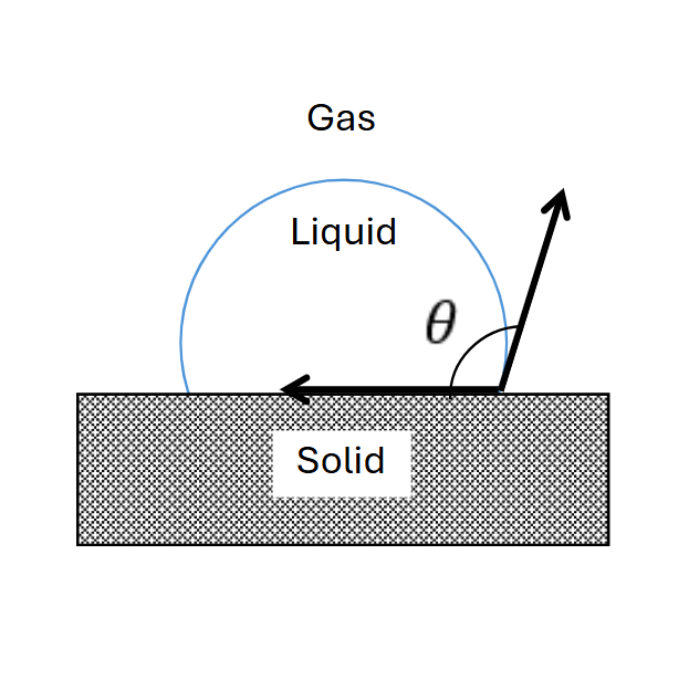
- Compute Contact Line Force
When this option is active, the model considers force arising from surface tension at the interface between the liquid, solid, and gas (headspace). This force is important when considering wetting, capillary action, and flow through microchannels. This force is relevant in microscale systems.
- Off
Do not consider contact line forces.
- On
Calculate contact line forces.
- Contact Angle
deg | This parameter defines the contact angle along the liquid, solid, gas contact line. In the figure below, the contact angle is defined by \(\theta\).
- Mount Point
m | The point about which torques and bending moments are computed for the static body.
- Fluid Interaction
Enable or disable interaction with fluid momentum. Disabling fluid interaction eliminates fluid interactions with the static body. This can be useful for modeling particle screens.
- Off
Interaction with fluid momentum is disabled.
- On
Interaction with fluid momentum is enabled.
Static Body Output Data
Static body output data include both 3D visualization files and ASCII text files. The output data written to both file types are determined by selections on the Static Body Output Control panel. Each static body family produces unique output files with file names linked to the dynamic name of the static body parent.
The 3D visualization files are binary .pvd files used for visualization, rendering, and analysis within M-Star Post. The data written to these files can include local fluid forces, local species fluxes, local fluid temperature, Static Body Variables, etc. These visualization files are written at both the Plane/Probe Output Write Interval and the Volume Output Write Interval, allowing for concurrent animation with any fluid, particle, or moving body dynamics.
Static body output data is printed to the Static Body Statistics file. The ASCII text files store the time-evolution of both raw and reduced output variables. These files can be explored within M-Star Post or opened in any text editor or spreadsheet tool. The data written to these text files can include total fluid forces, total species fluxes, mean fluid temperature along the static body, and the spatial mean of any static body variables. These text files are updated and appended at the Statistics Write Interval. A full preview and description of the data written to these files is available in the Statistics Output Data preview panel. If no output selections are made in the Static Body Output Control panel, no output text file will be produced.
Static Body Toolbar
Context-Specific Toolbar Forms |
Description |
|---|---|
|
The Add Geometry form adds child geometry by importing from external CAD files, extracting from external CAD assemblies, or defining internally using built-in parametric geometry. |
|
The Move form enables three-dimensional rigid body transform of object through free drag or point-to-point snapping. |
|
The Rotate form enables three-dimensional rotation of geometry. |
|
The Scale form enables volumetric scaling of a geometry about a set anchor point. |
|
The Edit Mesh form modifies the resolution of the solid body surface mesh used in the simulation. |
|
The Mate form allows surface-to-surface mating and alignment. |
|
The Add Static Body Reaction tool applies user-defined reaction kinetics to scalar fields along static body surfaces, computed voxel by voxel. |
|
The Add Static Body Variable tool defines voxel-based variables along static surfaces via UDFs, used to analyze near-wall fluid properties or deposition. |
|
The Add Patch tool is used to patch open regions in imported geometry. |
|
The Help command launches the M-Star reference documentation in your web browser. |
 Add Geometry
 Edit Mesh
 Add Static Body Reaction
 Add Static Body Variable
 Help
HelpSee also Child Geometry Context Specific Toolbar.
For a full description of each selection on the Context-Specific Toolbar, see Toolbar Selections.