 Refinement Zone
Introduction
Refinement zones are cuboid regions within the domain where the lattice realizes a step change in resolution and time step. The default cuboid lattice domain with uniform spacing is the most computationally efficient solution, although it may be memory inefficient. Adding local refinement can help to increase the memory efficiency of the code, but it is less computationally efficient than uniform grid spacing. Such zones are particularly useful in modeling systems with high aspect ratio features, such as small openings in large vessels or small impellers inside large tanks.
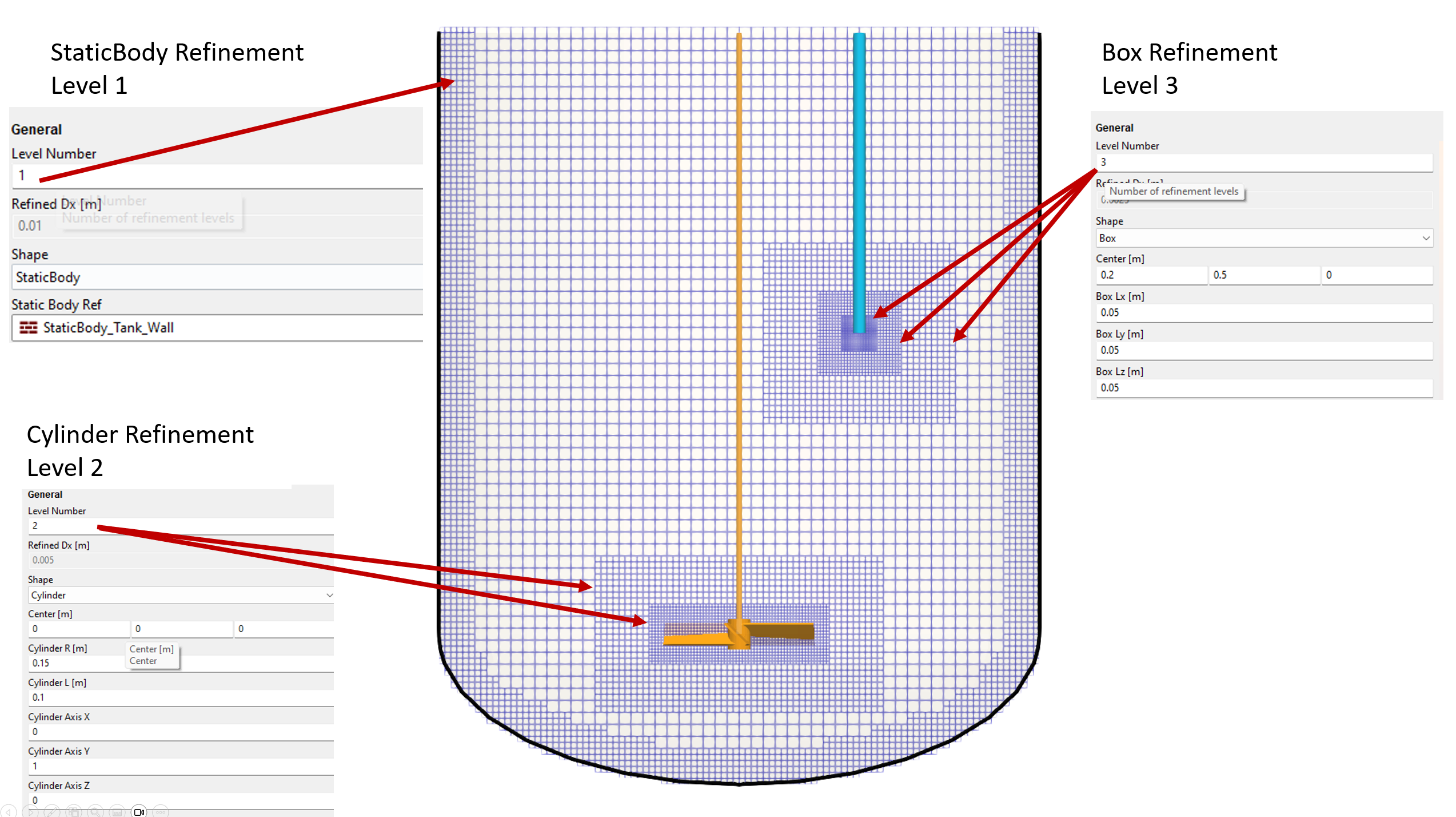
The image belows shows a side view of a tank which contains three refinement zones: the first zone is defined along the static body wall (the tank) and has level 1 refinement; the second zone is a primitive shape (a cylinder) which encases an impeller and has level 2 refinement; and the third zone is another primitive shape (a box) which encases a nozzle and has level 3 refinement.
Download Sample File: Refinement Zone
Each refinement zone is considered child to the main lattice parent. The child objects define the degree of refinement, as well as the extent of the local regiment region. The shape of a refinement zone can be defined using either (1) a reference static body geometry or (2) a primitive shape. In the first option, the shape of the refinement zone contours the children geometry of a user-referenced static body. The thickness of this refinement region (away from the wall) is then user-defined. This option is useful for increasing near to and along a solid surface. In the second option, the extent of the refinement zone is characterized by the form/volume of the selected primitive. This approach is useful for defining refinement around fully immersed objects, such as impellers and nozzles.
In cases where sufficient memory/hardware is unavailable and refinement is indeed necessary, care is required when defining the shape, extent, and degree of any refinement zone. When applied judiciously, refinement zones can offer multiple order-of-magnitude decreases in simulation runtimes, as compared to uniform mesh simulations.
Property Grid
General
- Level Number
This value defines the resolution of the lattice within the refinement zone. The lattice spacing is equal to the baseline resolution divided by \(2^{Level Number}\). For example, if the level number is set to 1, the resolution within the refinement zone will be 1/2 that of the far field. If the level number is set to 2, the resolution within the refinement box will be 1/4 that of the far field, etc.
If a refinement level greater than 2 is selected, the code will automatically add a set of transition layers that step down to the baseline resolution. These transitions layers will extend beyond the initial refinement zone.
The structure of the lattice can be previewed using the Preview Lattice Check command.
- Refined Dx
m | Read only. Lattice spacing within the refinement zone. This value cannot be edited directly, as it is defined by the baseline resolution and the specified level number.
Important
Above three or four boxes, the additional communication costs associated with each refinement box can exceed the computational savings associated with the reduction in total lattice count.
Refinement should be used as a mechanism for enhancing near field resolution, not starving the far-field resolution. If the far field is underresolved, spurious motions will appear at the boundaries of refinement zones.
- Shape
Shape of the refinement zone. This shape defines the extent of the local regiment region. The shape of the refinement zone can be defined using either a (i) box, (ii) sphere, (iii) cylinder, or (iv) static body surface. When a box, sphere, or cylinder is selected, the extent of the refinement region is defined by the location and the dimensions of the selected primitive. When a static body surface is selected, the refinement zone contours the children geometry of the user-referenced static body. The thickness of this refinement region (away from the wall) is then user-defined.
- Box
Box refinement zones are three-dimensional cuboids defined by a box center and box side length. Refinement boxes cannot be rotated. As such, the sides of the box are always aligned with the basis X, Y, and Z unit vectors defining the main lattice.
- Center
m | Center of the box refinement zone.
- Box Length X
m | X-side length of the box refinement zone.
- Box Length Y
m | Y-side length of the box refinement zone.
- Box Length Z
m | Z-side length of the box refinement zone.
- Sphere
Sphere refinement zones are three-dimensional spheres defined by a sphere center and a sphere radius. At runtime, the sphericity of the realized refinement zone surface will be correlated to the baseline resolution and the refinement level.
- Center
m | Center of the spherical refinement zone.
- Sphere Radius
m | Radius of the spherical refinement zone.
- Cylinder
Cylinder refinement zones are three-dimensional cylinders defined by a cylinder center, cylinder radius, and cylinder orientation. The orientation of the cylinder is defined by the components of the Cylinder Axis Vector. The components of this vector are defined relative to the basis X, Y, and Z unit vectors defining the main lattice.
- Center
m | Center of the cylinder refinement zone.
- Cylinder Radius
m | Radius of the refinement zone.
- Cylinder Length
m | Length of the refinement zone.
- Cylinder Axis Vector X
m | X component of the cylinder axis vector.
- Cylinder Axis Vector Y
m | Y component of the cylinder axis vector.
- Cylinder Axis Vector Z
m | Z component of the cylinder axis vector.
- Static Body
When a static body surface is selected, the refinement zone contours all children geometry of the user-referenced static body. The thickness of this refinement region (away from the wall) is then user-defined.
- Static Body Reference
Link refinement zone to a static body parent. The refinement zone will contour all children geometry associated with the static body parent.
- Refine Distance
m | Thickness of the refinement region along the children geometry.
Note
The Cylinder Axis Vector only defines the orientation (not the length of the cylinder refinement zone). At runtime, the Cylinder Axis Vector is normalized to define a unit vector. This normalized axis vector, combined with the user-specified cylinder length and radius, define the extent of the cylinder.
Refinement zones define using a static body will not be shown in the 3D view. The structure of the lattice can be previewed, however, using the Preview Lattice Check command.
Display Attributes
- Visible
The ability to show or hide the object.
- Shown
The object is shown in the 3D view.
- Hidden
The object is hidden in the 3D view.
Refinement Zone Toolbar
Context-Specific Toolbar Forms |
Description |
|---|---|
|
The Help command launches the M-Star reference documentation in your web browser. |
 Help
HelpFor a full description of each option, see Context-Specific Toolbar selections.