 Inclusion Zone
Introduction
Inclusion zones are regions of the domain where the solver will explicitly place lattice points. Regions outside the inclusion zones are not considered as part of the simulation. This trimming effect reduces the number of lattice points stored in the system memory. This feature is particularly useful for systems with winding pipe geometries or cone-type vessels, where the fluid volume is small compared to the main lattice volume. Multiple inclusion zones can be added to a single system, allowing users to trim the mesh to follow complex geometry.
Download Sample File: Inclusion Zone Default Setup
Download Sample File: Inclusion Zone Enabled
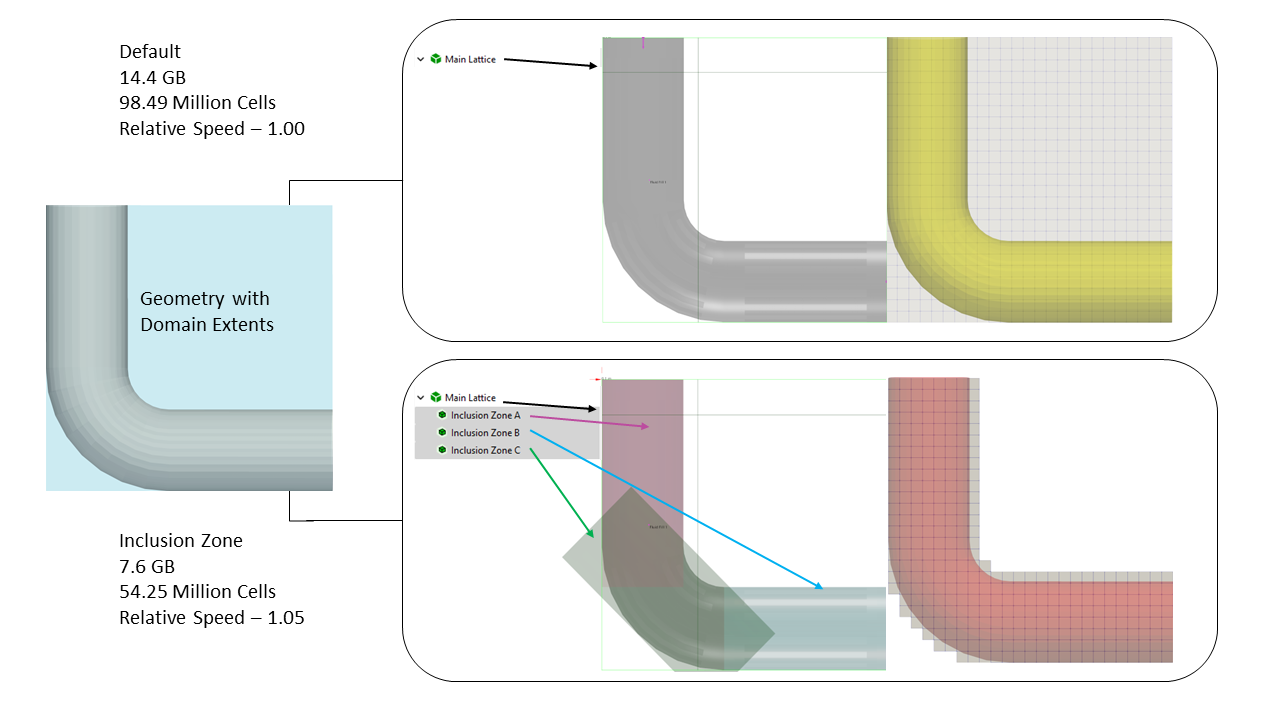
In the figure above, we compare the lattice generated for a pipe elbow with and without inclusion zones. In the system without inclusion zones, the main lattice is cuboid and includes the full extent of the exterior zone. In the system with inclusion zones, which are appropriately tailored to follow the contours of the elbow, the lattice excludes a majority of the exterior zone. For this case, the user-defined inclusion zones reduce the memory requirements by 40% (as compared to the default lattice). Beyond this simple example, inclusion zones can generate multiple order-of-reductions in memory requirements for more complex piping networks.
Understanding the utility of inclusion zones requires understanding the action of the flood fill and difference between the interior and exterior zones. The interior zone, as illustrated above, is the space inside a vessel, pipe, or bounding geometry. The exterior zone is the region of the main lattice outside tank/pipe walls.
By default, the solver allocates memory for the entire computational domain, encompassing both the interior and exterior zones. While this uniform memory allocation maximizes computational efficiency, it can lead to significant memory overhead when the volume of the interior zone is small compared to the exterior zone. In such cases, the inclusion zone feature provides a mechanism for optimizing memory usage.
By explicitly defining the interior zone where fluid flow is relevant, the solver allocates memory for only this region, significantly reducing memory requirements. This results in a smaller memory footprint and the ability to run larger simulations with larger domain sizes or finer resolutions within available memory resources. The use of the inclusion zone feature is highly recommended when the interior zone volume is significantly smaller than the exterior zone volume and may be necessary in some cases to fit the simulation within available memory constraints.
Each inclusion zone is considered child to the main lattice parent. Inclusion zones can be defined using either box, cylinder, or sphere geometry. The resulting structure of the lattice generated by the inclusion zones can be previewed using the Preview Lattice Check command.
Property Grid
General
- Shape
Shape of the inclusion zone. This shape defines the extent of the local regiment region. The shape of the inclusion zone can be defined using either a (i) box, (ii) sphere, (iii) cylinder, or (iv) static body surface. When a box, sphere, or cylinder is selected, the extent of the inclusion region is defined by the location and the dimensions of the selected primitive. When a static body surface is selected, the inclusion zone contours the children geometry of the user-referenced static body. The thickness of this inclusion region (away from the wall) is then user-defined.
- Box
Box inclusion zones are three-dimensional cuboids defined by a box center and box side length. Inclusion boxes cannot be rotated. As such, the sides of the box are always aligned with the basis X, Y, and Z unit vectors defining the main lattice.
- Center
m | Center of the box inclusion zone.
- Box Length X
m | X-side length of the box inclusion zone.
- Box Length Y
m | Y-side length of the box inclusion zone.
- Box Length Z
m | Z-side length of the box inclusion zone.
- Cylinder
Cylinder inclusion zones are three-dimensional cylinders defined by a cylinder center, cylinder radius, and cylinder orientation. The orientation of the cylinder is defined by the components of the Cylinder Axis Vector. The components of this vector are defined relative to the basis X, Y, and Z unit vectors defining the main lattice.
- Center
m | Center of the cylinder inclusion zone.
- Cylinder Axis Vector X
m | X component of the cylinder axis vector.
- Cylinder Axis Vector Y
m | Y component of the cylinder axis vector.
- Cylinder Axis Vector Z
m | Z component of the cylinder axis vector.
- Cylinder Length
m | Length of the inclusion zone.
- Cylinder Radius
m | Radius of the inclusion zone.
- Sphere
Sphere inclusion zones are three-dimensional spheres defined by a sphere center and a sphere radius. At runtime, the sphericity of the realized inclusion zone surface will be correlated to the baseline resolution.
- Center
m | Center of the spherical inclusion zone.
- Sphere Radius
m | Radius of the spherical inclusion zone.
Display Attributes
- Visible
The ability to show or hide the object.
- Shown
The object is shown in the 3D view.
- Hidden
The object is hidden in the 3D view.
- Mode
Offers two options to view the inclusion zone.
- Wire
Wire frame.
- Shaded
3D shaded mode.
- Color
Customize the color of the inclusion zone.
- Width
Customize the width of the inclusion zone.
Note
The Cylinder Axis Vector only defines the orientation (not the length of the cylinder inclusion zone). At runtime, the Cylinder Axis Vector is normalized to define a unit vector. This normalized axis vector, combined with the user-specified cylinder length and radius, define the extent of the cylinder.
Inclusion zones define using a static body will not be shown in the 3D view. The structure of the lattice can be previewed, however, using the Preview Lattice Check Command.
Inclusion Zone Toolbar
Context-Specific Toolbar Forms |
Description |
|---|---|
|
The Help command launches the M-Star reference documentation in your web browser. |
 Help
HelpFor a full description of each option, see Context-Specific Toolbar selections.