 Define Axis
Introduction
The Define Axis form allows you to specify the mount point and rotation axis. See also Defining Motion Vectors. Whenever a moving body is imported from CAD, the user is automatically prompted to the Define Axis form.
Access
When you select Define Axis on a moving body context-specific toolbar, the form below will launch.
Define Axis Form
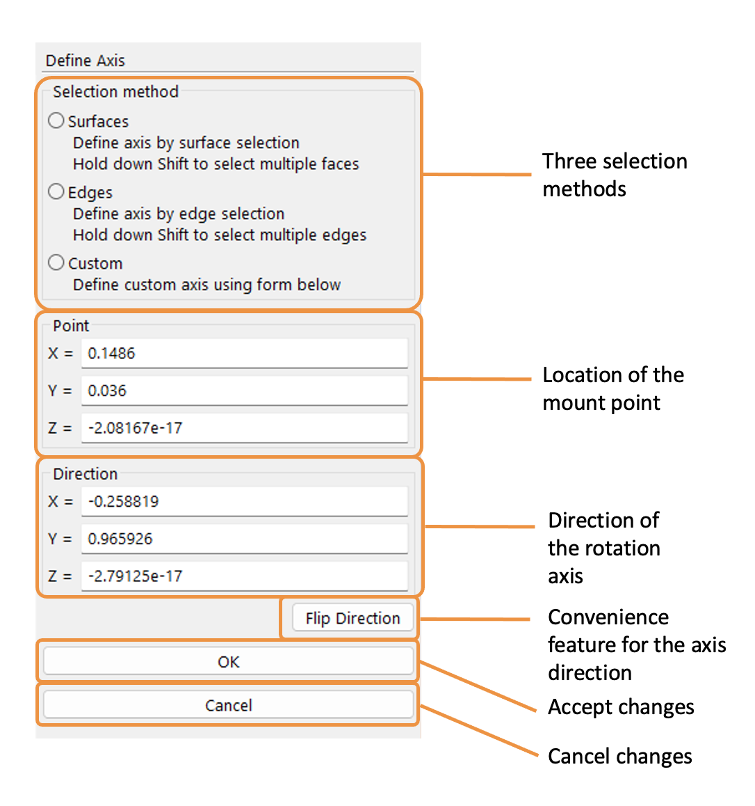
Selection Method
- ○ Surfaces
User selects a surface of the CAD geometry. The mount point is positioned at the center of this surface and the rotation axis is defined as the unit vector normal to the surface. Hold down the Shift button to select multiple faces when defining the surface. The surface must be planar. The candidate axis is shown in green in the 3D viewing panel. For reference, the corresponding mount point and rotation axis are listed in the form.
- ○ Edges
User selects a closed edge of the CAD geometry. The mount point is positioned at the centroid of the surface defined by the edge. The rotation axis is then defined as the unit vector normal to the surface defined by the edge. Hold down the Shift button to select multiple edges to define a closed loop. All selected edges must occupy the same plane. The candidate axis is shown in green in the 3D viewing panel. For reference, the corresponding mount point and rotation axis are listed in the form.
- ○ Custom
User manually specifies the mount point and rotation axis. The candidate axis is shown in green in the 3D viewing panel.
Point
Location of the mount point. When selecting surfaces or edges, this is automatically defined; when using custom, the user can define this point.
- X=
X location of the mount point.
- Y=
Y location of the mount point.
- Z=
Z location of the mount point.
Direction
Direction of the rotation axis (X, Y, Z). When selecting surfaces or edges, this is automatically defined; when using custom, the user can define the direction.
- X=
X direction of the rotation axis.
- Y=
Y direction of the rotation axis.
- Z=
Z direction of the rotation axis.
- Flip Direction
This button is a convenience feature to flip the axis direction.
- Cancel
This button cancels the changes to define axis and closes the form.
- OK
This button accepts the changes to define axis and closes the form.
Tip
See also Importing CAD geometry tutorial.
Location
The Define Axis form is found on the following context-specific toolbars (accessed through the Create menu):
