Parametric Pipes
These are the parameters that define the child geometry. The categories, settings, and/or selections available within the property grid depend on the child geometry type, as listed in the catalog.
Property Grid
General
- Location
This parameter defines the position of the geometry mount point within the domain. Editing this value adjusts the location of the geometry within the domain.
If an object is selected from the Parametric Primitives group, the following setting will launch.
- Primitive Type
This parameter defines how the primative geometry is filled. Two options are available: shell and solid. These options inform the behavior of the Trim command.
- Shell
This defines the primitive as a zero-thickness surface.
- Solid
This defines the primitive as a filled solid object.
Shape Parameters
These are the parameters that define the child geometry. The exposed parameters will depend on the geometry type, as listed below.
Catalog
Bend Pipe
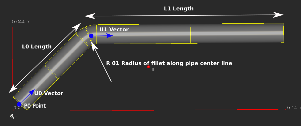
The bend pipe is defined by 2 or more segments. Consequtive segments are connected to each other by fillet radius. The resulting curve is used as a sweep curve for an extrusion, creating the pipe geometry. The pipe has a constant diameter.
Each segment is defined with a Unit Vector and Segment Length. A Bend Radius defines the fillet radius between the segment and the previous segment. For example, Bend Radius 1 defines the fillet radius between segments 0 and 1.
The pipe starts at the Start Point.
- Capped Start
Option to turn On or Off a capped end
- Capped End
Option to turn On or Off a capped end
- Start Point
The start location of segment 0
- Unit Vector 0
Direction vector for segment 0
- Segment Length 0
Length of segment 0
- Unit Vector 1
Direction vector for segment 1
- Segment Length 1
Length of segment 1
- Bend Radius 1
Fillet radius between segment 0 and 1. In order for the extruded pipe face to remain aligned with the segment direction, a positive value must be entered.
Note
More segments may be available depending on variant of Bend Pipe selected
Bifurcation Pipe
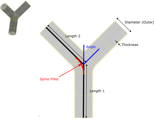
- Diameter
Outer diameter of pipe
- Thickness
Thickness of pipe wall
- Length1
See diagram
- Length2
See diagram
- Spine Fillet
See diagram
- Angle
See diagram
Spline Pipe
The spline pipe geometry uses a 2nd degree b-spline to construct a curve. The points P0, P1, and P2 define the control polygon of the spline curve. A circular contour is then swept over the resulting curve, defining the spline pipe geometry.
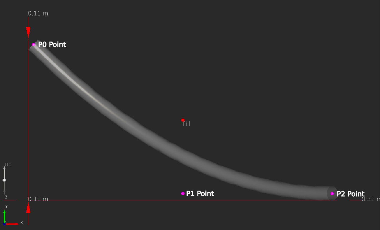
- Diameter
Pipe diameter
- Capped Ends
Option to have solid or empty ends
- P0
Spline control point
- P1
Spline control point
- P2
Spline control point
T-Junction Pipe
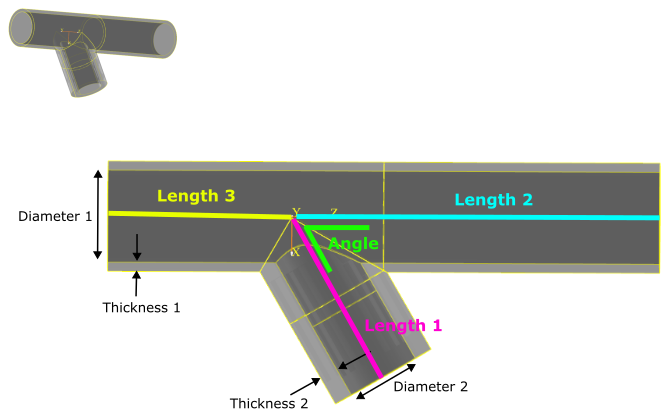
- Diameter 1
See diagram
- Thickness 1
See diagram
- Length 2
See diagram
- Length 3
See diagram
- Diameter 2
See diagram
- Thickness 2
See diagram
- Length 1
See diagram
- Angle
See diagram