Advanced Rendering with Ray Tracing in M-Star Post
Overview
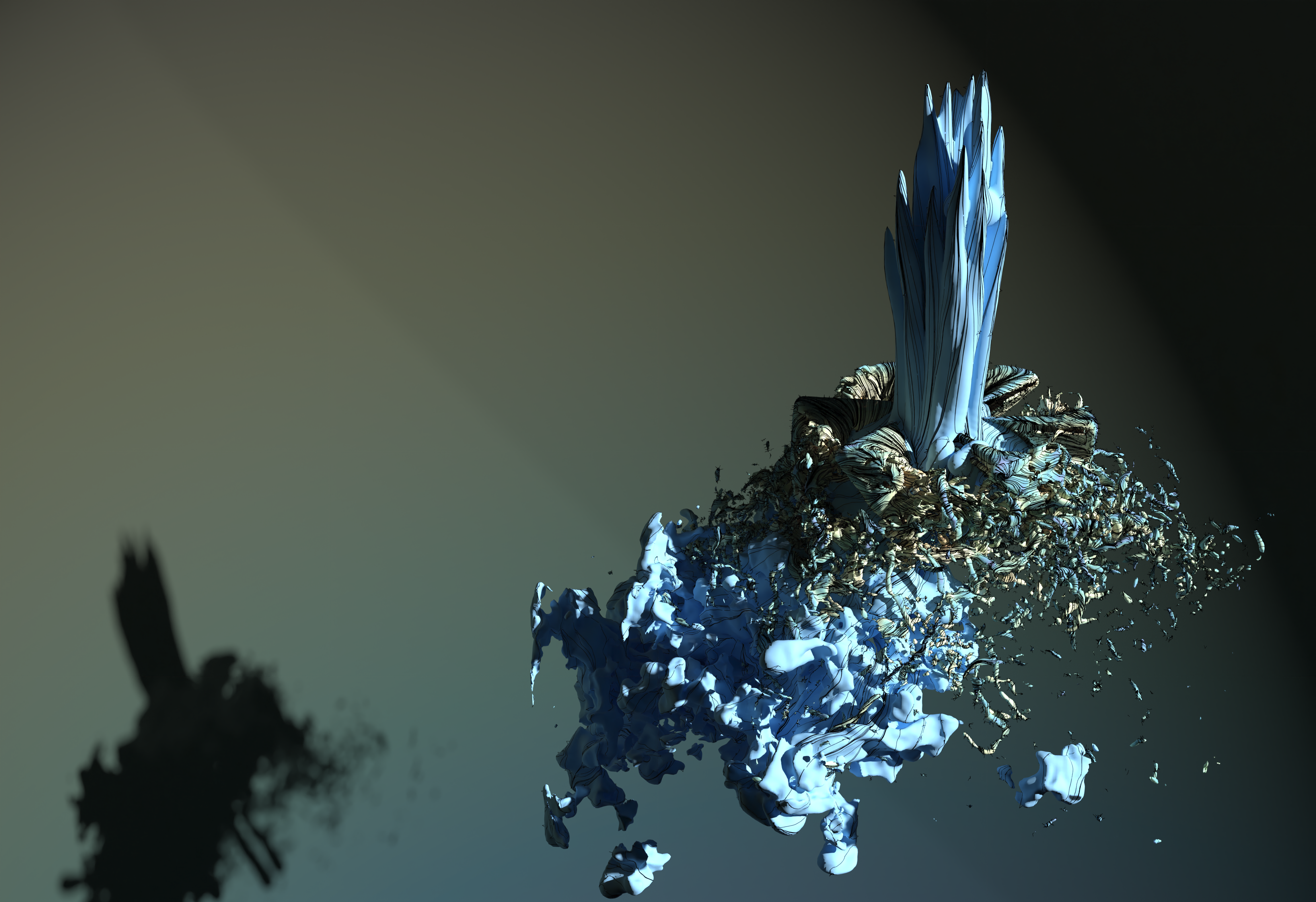
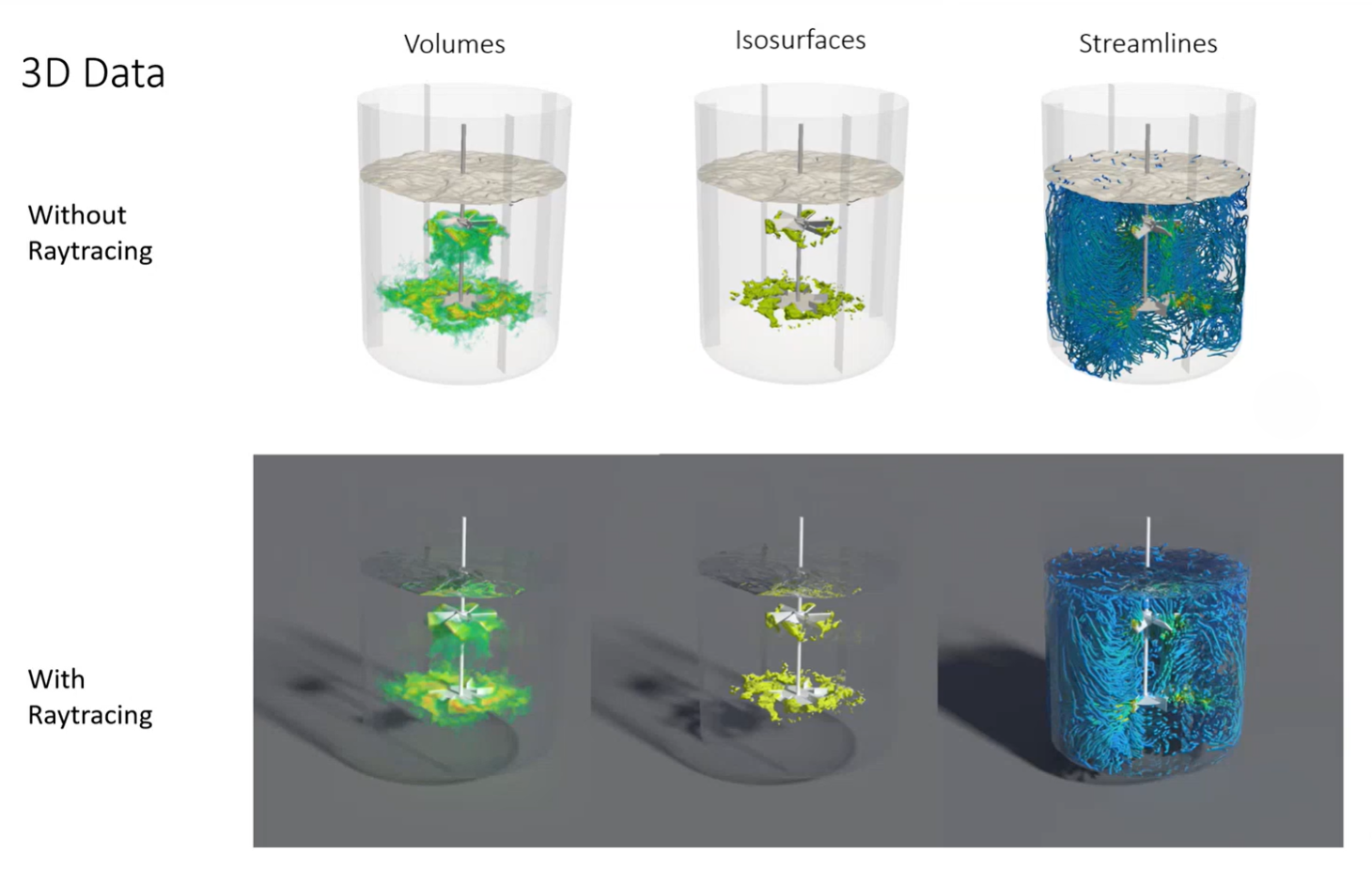
The goal of this tutorial is to transform standard CFD visualizations into photorealistic, high-impact renders. By leveraging ray tracing—a technique that simulates the physical behavior of light by tracing rays backward from the camera to the source—users can achieve a sense of depth, realistic shadowing, and material accuracy that standard rendering cannot provide.
Getting Started
Prerequisites:
M-Star Post or ParaView installed
A GPU capable of hardware acceleration (e.g., NVIDIA RTX series) for optimal performance
CFD dataset (volumetric data, particles, or slices)
Cleaning Up 2D Slices with Thresholding
Before moving into complex 3D scenes, it is essential to ensure that 2D slices are clean and free of artifacts. When using features like Surface LIC (Line Integral Convolution), the software often renders data in empty cells outside the actual fluid domain, which can be visually distracting.
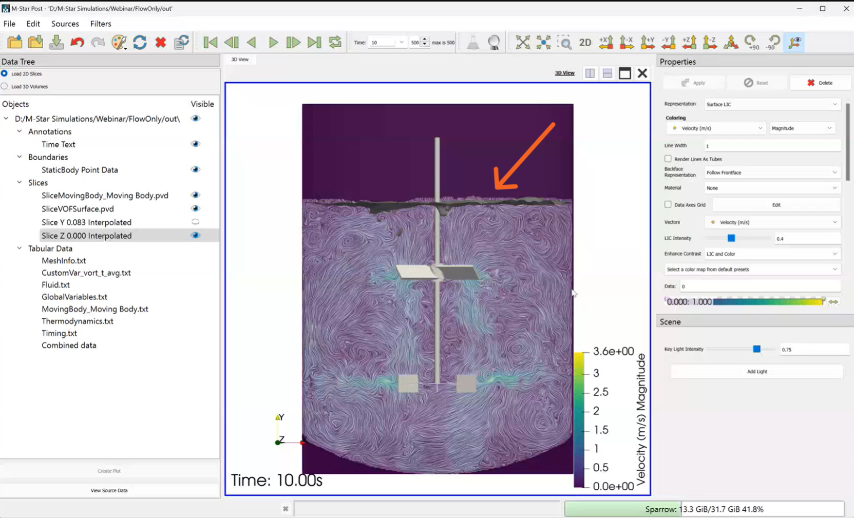
Select the Threshold filter from the menu.
Choose a variable such as Volume Fraction.
Set the range from 0.5 to 1.0 (or above) to isolate the fluid phase and remove empty cells.
Apply a Diverging Color Scheme for velocity plots, using colors like blue for descending fluid and red for ascending fluid to clearly communicate flow direction.
Attention
Save your state file frequently. Complex scenes are more prone to crashing during the initial render setup.
Tip
Use a symmetrical color scale when plotting data that ranges from negative to positive values to ensure the zero-point remains visually centered.
Enabling Ray Tracing
Ray tracing works “backwards” from the camera, tracing rays into the scene to determine what is visible. This avoids wasting computation on irrelevant areas but is significantly more expensive than standard rasterization.
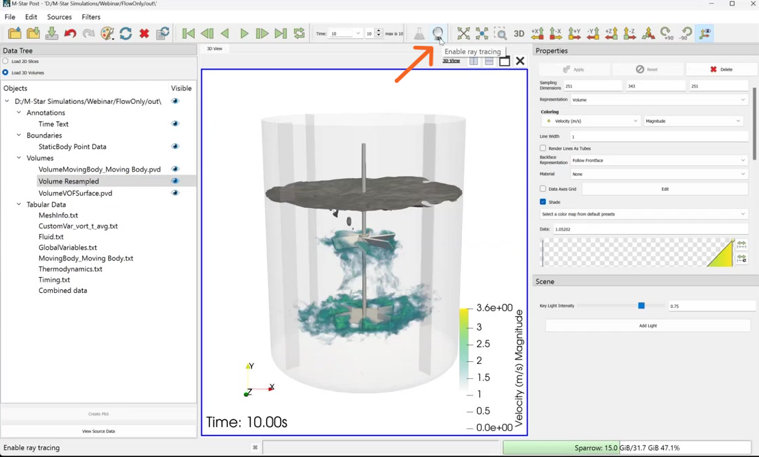
Locate and click the Enable Ray Tracing button.
Adjust the Samples per Pixel. This determines how many primary rays are shot into the scene; higher values increase sharpness and reduce noise but significantly increase render time.
Set a balanced value based on your hardware (e.g., a gaming laptop with an RTX GPU can handle moderate to high samples).
Tip
Always deactivate ray tracing mode while rotating, zooming, or navigating the scene. Ray tracing is computationally expensive and will make real-time interaction painfully slow.
Setting Up the Scene Background
A realistic image requires an environment for the object to sit in. Without a background, objects appear to float in a void, and you lose the ability to see grounded shadows.
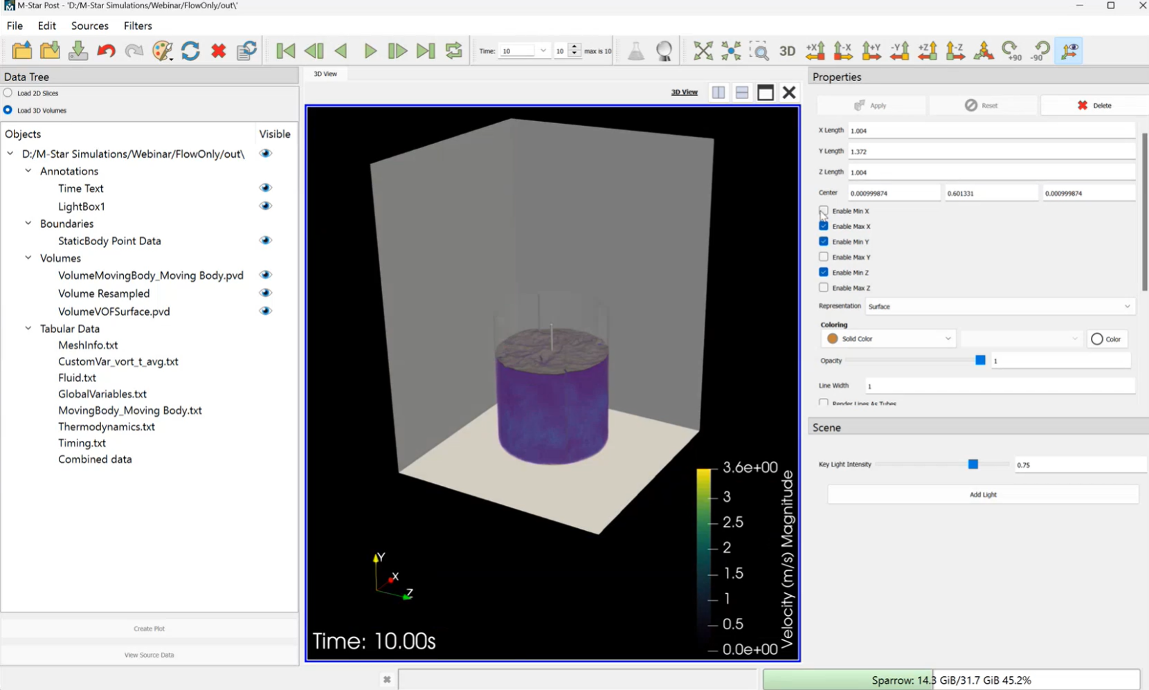
Navigate to the Scene settings.
Select and apply a Light Box. This creates a controlled studio environment with walls.
Adjust the X and Z length of the light box to ensure the background is large enough to encompass your model without feeling cramped.
Toggle specific walls on or off depending on the desired composition.
Enhancing the Scene
Configuring Custom Light Sources
The default “Key Light” is often insufficient for high-end renders. Creating a custom light source allows you to control the mood, depth, and the focal point of the image.
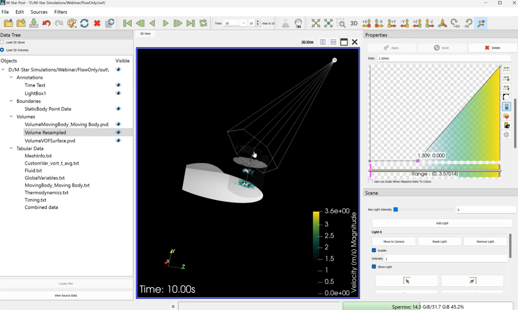
Deactivate the default key light.
Select Add Light and choose a positional light source.
Move the Source and Focal Point to angle the light across the object, which helps define its three-dimensional shape through highlights and shadows.
Softening Shadows via Bottom Radius
By default, point lights create unnaturally sharp shadows. In the real world, light sources have physical dimensions, which results in “soft” edges (penumbras) on shadows.
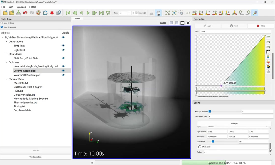
Locate the Bottom Radius setting for your custom light.
Increase this value (e.g., to 0.1) to simulate a larger physical light source.
Observe how the shadows transition from a hard line to a natural, soft gradient.
Applying Materials and Isosurfaces
Ray tracing allows you to assign real-world material properties to your data. Without ray tracing enabled, changes to material settings will have no visible effect on the render.
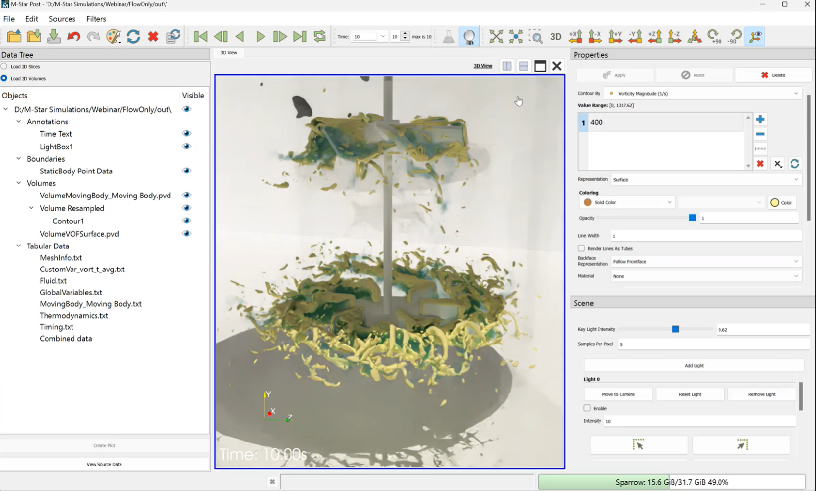
Select the object (e.g., a volume or surface) and navigate to Material.
For free surfaces or droplets, choose materials like Glass or Air-Water Interface to achieve realistic reflections and refractions.
Use a Contour Filter to create Isosurfaces of variables like vorticity. This creates high-contrast regions that interact beautifully with the light source.
Note
Ray tracing is iterative. The image will appear grainy at first but will gradually refine and become smoother the longer you leave it to render.
Adding High-Fidelity Streamlines
Streamlines add a dynamic element to the scene. Because ray tracing handles thickness and opacity differently than standard rendering, these must be tuned specifically for the final output.
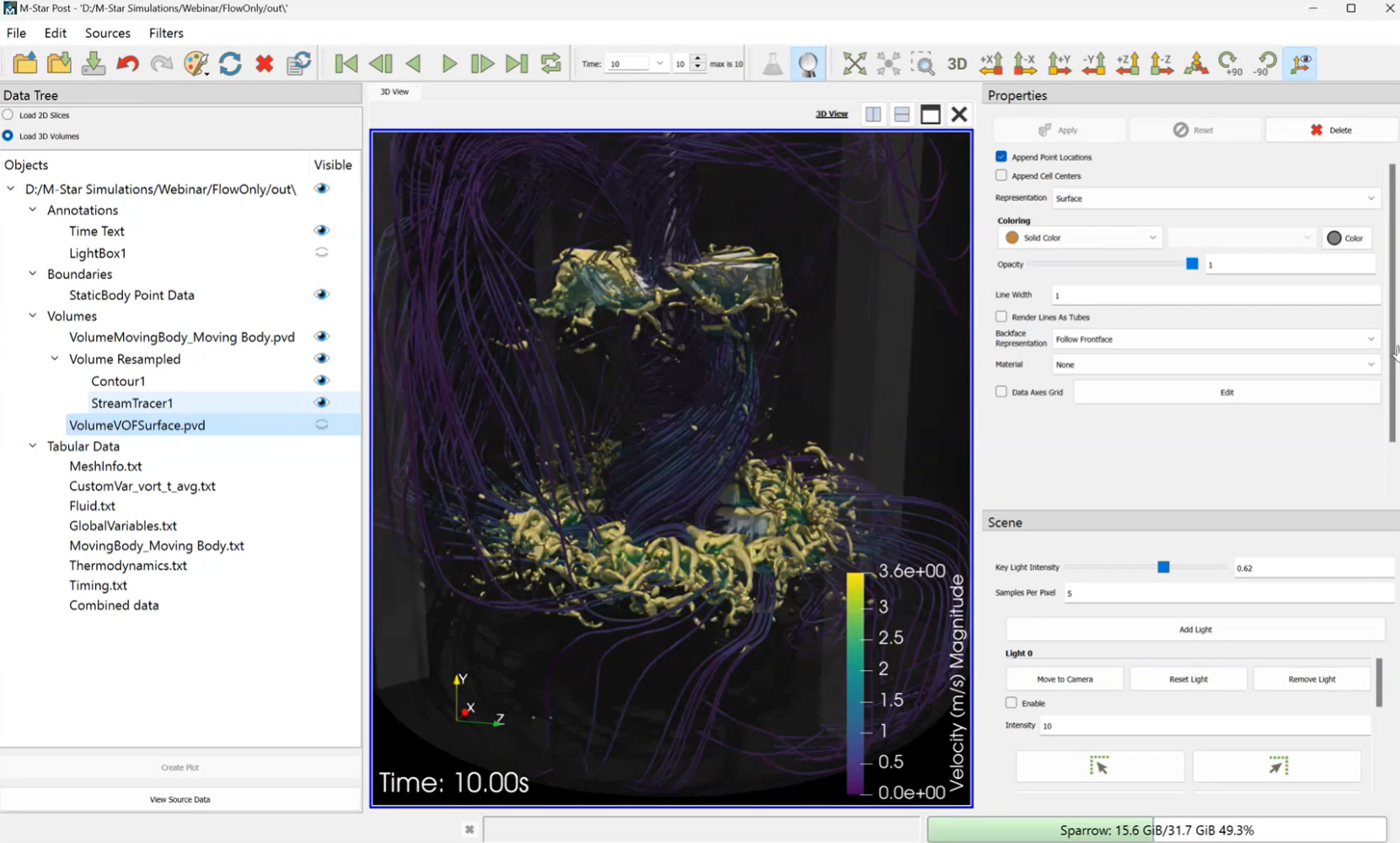
Use the Stream Tracer filter.
Define the seed points using a Point Cloud or Sphere. You can adjust the size and position of this sphere using the mouse to capture the most interesting part of the flow.
Deactivate the opacity map if the streamlines are too faint to see.
Rendering Specialized Data
Rendering High-Quality Particles
Ray tracers cannot render “points” because they require surfaces (faces) to reflect light. To render particles, you must convert them into 3D geometry.
Open your PVD particle files in ParaView.
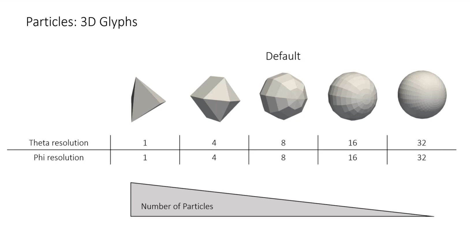
Apply a Glyph Filter and select Spheres.
Set the Scale Array to Diameter and adjust the scale factor (e.g., 1.0) so particles are visible.
For a small number of particles (a few thousand), increase the resolution (e.g., 16 × 16 perfectly smooth).
Applying Glass Materials to Particles
To make particles look like droplets or glass marbles, you can apply specific refractive materials in ParaView.
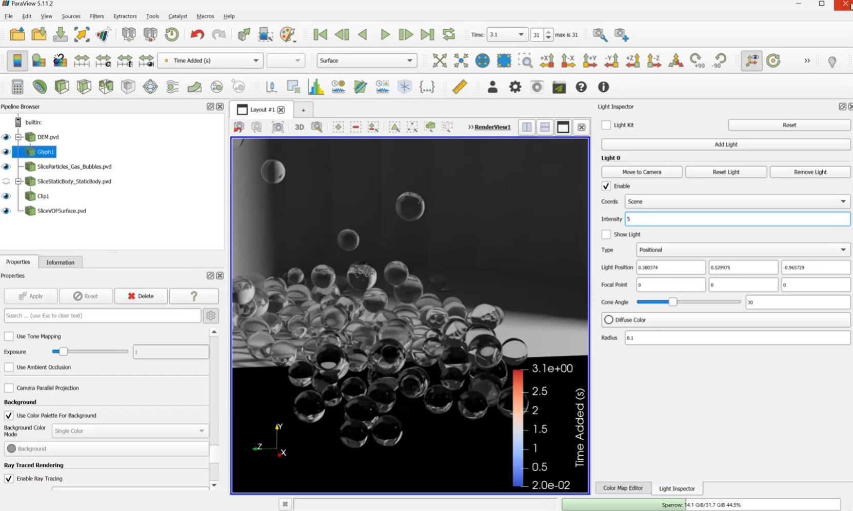
In the Material settings, select Glass (or “Glass Thick”).
Ensure the ray tracer is set to Osprey Path Tracer, as it handles volume and refraction more accurately than other renderers.
The particles will now exhibit realistic transparency and light bending.
Optimizing Large Particle Sets (1M+ Particles)
Rendering a million high-resolution spheres will crash most workstations. To handle massive datasets, you must trade off individual particle quality for overall scene performance.
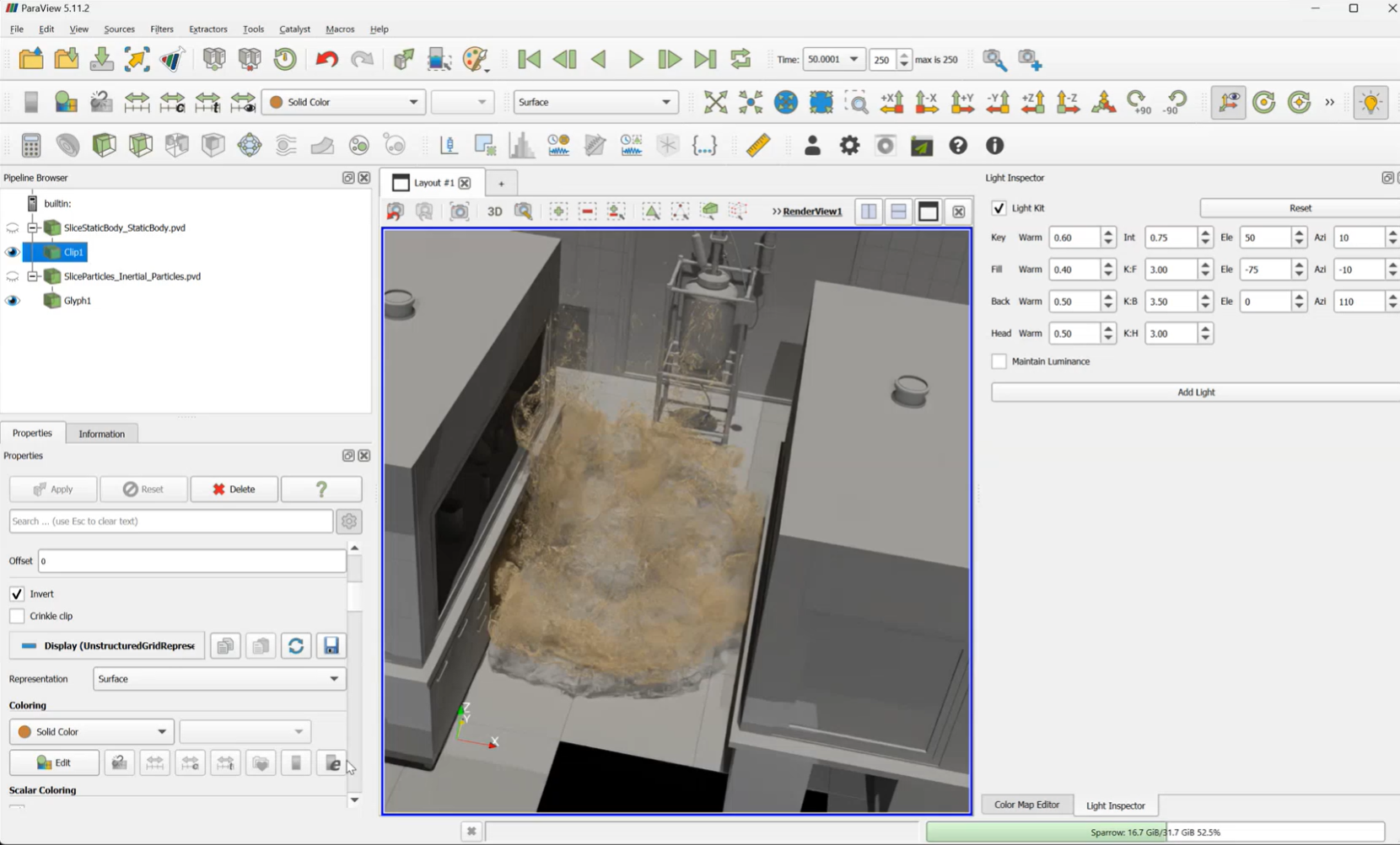
Use the Glyph Filter but keep the resolution low (coarse spheres).
From a distance, coarse spheres are indistinguishable from high-resolution ones but render significantly faster.
Ensure Show All Points is selected to avoid automatic downsampling by the software.
Creating Luminous Objects
You can turn any object—including particles or geometry—into a light source. This allows you to create glowing effects without needing an external lamp
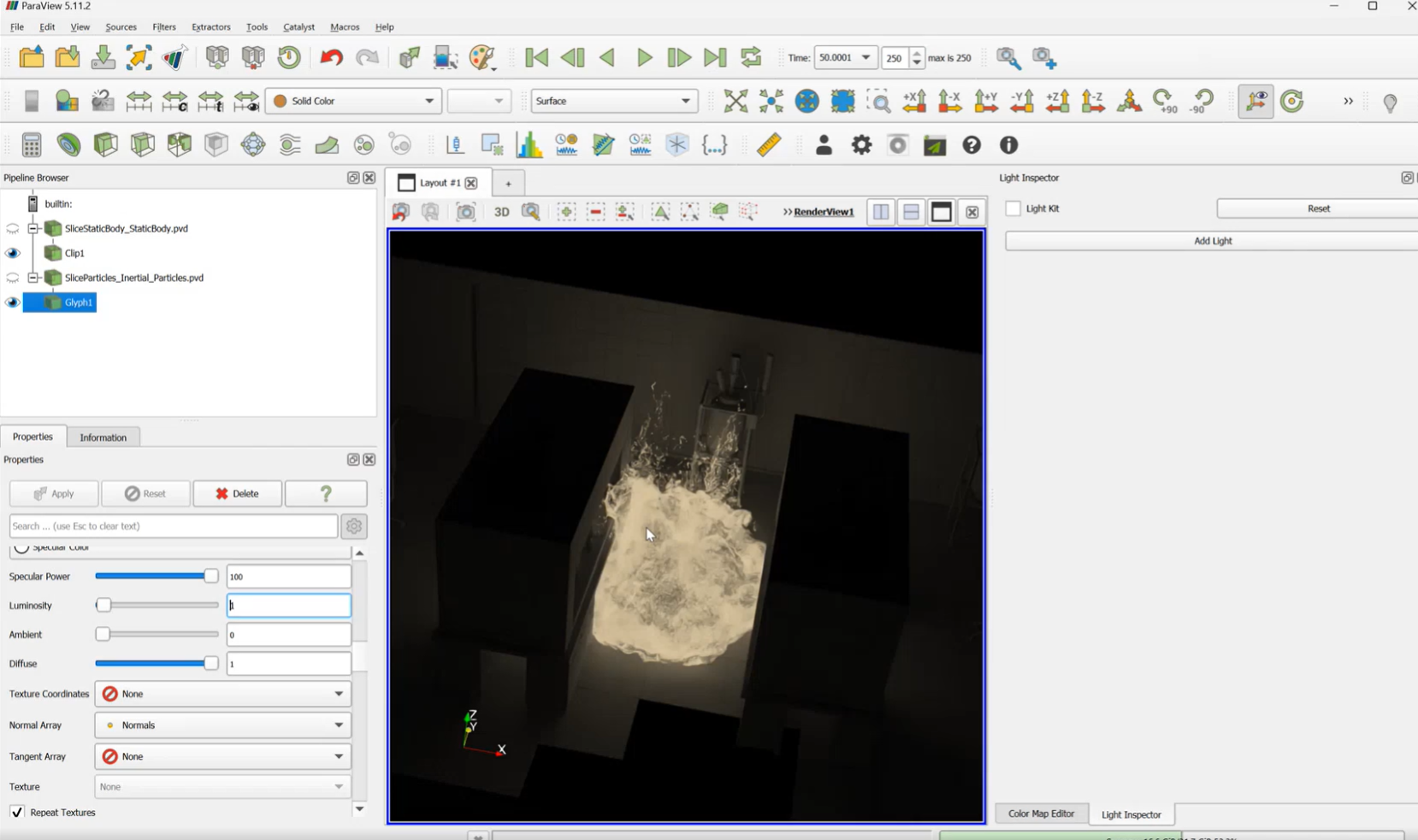
Select the object you wish to make glow.
In the properties, find Luminosity.
Set the value to greater than 1.
Turn off all other scene lights to see the effect; the luminous objects will now cast light onto surrounding surfaces and other particles.
Animation
Calculating Animation Output Frequency
When creating movies, the “smoothness” depends on the output frequency of your data frames. You must calculate the time step (Δt) based on the physical rotation or process speed to avoid choppy animations.
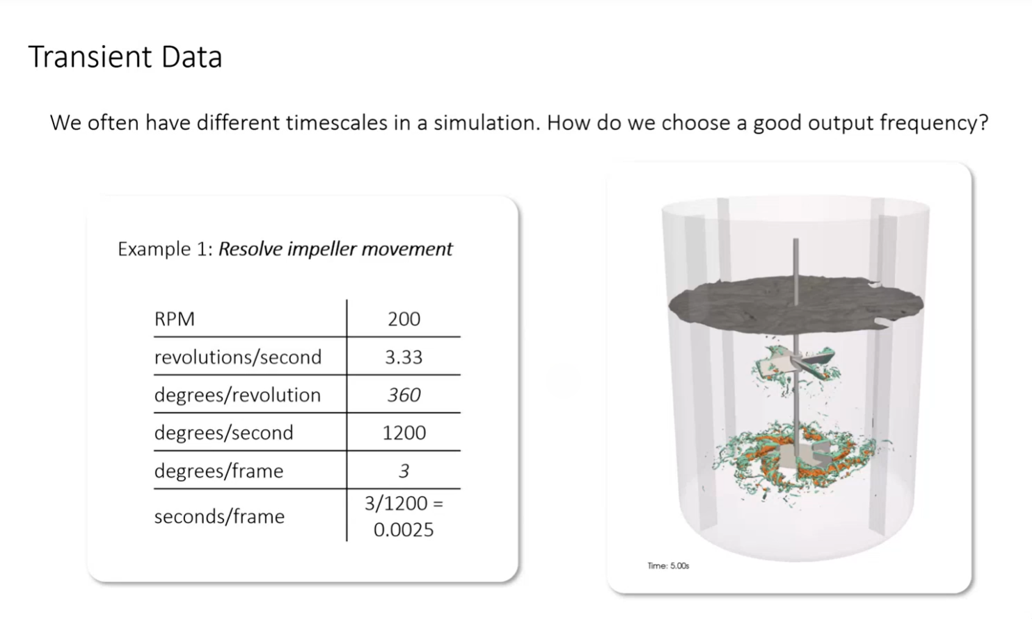
Determine Rotation Speed: For a 200 RPM impeller, this is 3.3 revolutions per second (120∘ per second).
Set Target Frame Rate: If rendering at 30 FPS and wanting the impeller to move only 3∘ per frame, calculate the required data frequency.
Formula for Process Time: Total Frames = Desired Movie Duration (s) × FPS
Divide your total process time by the total frames to find the exact output frequency needed during the simulation setup.
Summary
By following these steps, you have moved from basic data plotting to professional scientific visualization. You have learned how to:
Clean data using threshold filters to remove domain artifacts.
Build a studio environment using Light Boxes and custom positional lights.
Enhance realism by adjusting light radii for soft shadows and applying physical materials (Glass/Water).
Optimize performance by balancing sample counts, disabling ray tracing during navigation, and reducing glyph resolution for large particle sets.
Calculate animation timing to ensure physics are captured smoothly at a specific FPS.
Create advanced effects such as luminous objects and high-contrast isosurfaces
Additional Resources
For more on this subject, check out the following:
Webinars
Photorealistic Rendering of Simulations: How M-Star Makes Incredible Movies